
Table of Contents
1. Introduction
2. Definitions of fluid mechanics, fluid statics and fluid dynamics.
5. Specific Gravity or Relative Density
6. Density of mixture of fluids
7. Pascal’s Law
8. Atmosphere Pressure and Barometer
9. Manometer
10. Hydraulic Machine, principle & application
11. Hydraulic Lift
12. Hydraulic Brakes
13. Other applications of Hydraulic Machine
14. Buoyant Force
15. Derivation of Buoyant Force
16. Archimede’s principle and special Cases
17. Real life examples of Archimede’s principle: (i) Why does a stone sink?
(ii) Why does a heavy ship float?
20. Bernoulli’s Equation and it’s derivation
21. Applications of Bernoulli’s principle
22. Speed of Efflux Torricelli’s Law
23. Venturimeter
24. Pitot’s Tube
25. Other Real-Life Examples of Bernoulli’s principle
26. Equation of Continuity and it’s Derivation
27. Applications of Equation of Continuity
28. Streamline Flow
29. Turbulent Flow
Introduction
In this chapter we shall study some common physical properties of liquids and gases. Liquids and gases can flow and are therefore called Fluids. It is this property that distinguishes liquids and gases from solids in a basic way. Fluid state means a substance which begins to flow when external force is applied on it.
In liquids, the inter molecular distances are generally larger than in solids. Hence the intermolecular forces tend to be weaker in liquids than in solids. Many liquids are, like solids, relatively incompressible (i.e. their volumes do not change much with variation in pressure). So liquids cannot support shearing stresses, because layers of the liquid can easily slide over one another.
In gases, the molecules interact only weakly, and therefore gases are unable to transmit shearing stresses. Gases generally are far more compressible (i.e. their volumes vary with pressure) than solids or liquids.
The key property of fluids is that they offer very little resistance to shear stress i.e. their shape changes by application of very small shear stress. The shearing stress of fluids is about million times smaller than that of solids. An ideal fluid offers no resistance to the shearing force at all.
what is Fluid Mechanics ?
The branch of physics which deals with the fluids either at rest or in motion is called fluid mechanics.
What is Fluid Statics ?
The branch of fluid mechanics that deals with a fluid at rest is called Fluid Statics. Study of water at rest is called Hydrostatics. It includes Fluid Pressure, Pascals Law, Archimedes Principle etc.
What is Fluid Dynamics ?
The branch of fluid mechanics which deals with the fluids in motion is called fluid dynamics.
What is Pressure ?
Pressure is defined as the force acting normal to a unit surface area.
P = F/A
- Pressure is a Scalar Quantity.
- S.I unit : N/m² or Pascal (Pa),
- C.G.S unit : dyne/cm².
- 1 dyne/cm² = 10⁻¹ N/m²
- Dimensional formula : M¹L⁻¹T⁻²
- Atmospheric pressure can be determined using Fortin’s Barometer.
- 1 atmosphere = 1.013 × 10⁵ Pa = 1.013 bar.
Examples of Pressure
1. A sharp blade is more effective in cutting an object than a blunt blade. This is because the blunt blade transmits force over a larger area compared to a sharp blade. So, the pressure in the latter case is more than in the former case.
2. It is difficult for a man to walk on sand but a camel walks easily on sand despite the fact that camel is much heavier than man. This is because camel’s feet have a larger area than the feet of man. Due to larger area, pressure is less.
3. When we stand on both feet, the pressure produced on the ground will be less than if we stand on one foot.
Density of a Fluid
Density of the fluid is defined as the ratio of mass to volume occupied by the fluid. Density is an important quantity for description of fluids.
ρ = m / V
- Its S.I unit : kg/m³,
- C.G.S unit : g/cc and
- 1 g/cc = 10³ kg/m³
- Density is a macroscopic property.
Density of a fluid determines the inertia of the fluid. A low density fluid like air, requires less force per unit volume to accelerate it than does a high density fluid like water.
In case of a homogeneous and isotropic substance, density is same in all directions.
When immiscible liquids of different densities are poured in a container, the liquid of highest density will reach the bottom while that of the lowest density will reach the top, at stable equilibrium. The interface will be plane.
What is Specific Gravity or Relative Density (SG) of Fluids?
It is defined as the ratio of the density of a given substance to the density of water at 4°C.
∴ SG = ρsubstance / ρwater at 4°C
- Since SG is a ratio, it has no units and no dimensions.
- As ρwater in C.G.S system is 1 g cm⁻³,
- SG of substance = ρ of substance in C.G.S system.
- At 40C, the density of water is 1000 kg/m3.
Density of a Mixture of fluids?
a) When two liquids of masses m₁, m₂ and densities ρ₁, ρ₂ respectively are mixed, then the effective density of the mixture is
ρ = M/V
= (m₁ + m₂) / (V₁ + V₂)
= (m₁ + m₂) / [(m₁/ρ₁) + (m₂/ρ₂)]
= ((m₁ + m₂)ρ₁ρ₂) / (m₁ρ₂ + m₂ρ₁)
Note: i) If m₁ = m₂,
then, ρ = 2ρ₁ρ₂ / (ρ₁ + ρ₂) (harmonic mean)
ii) For mixture of any number of liquids:
ρ = Σmᵢ / Σ(mᵢ/ρᵢ)
b) When two liquids of volumes V₁, V₂ and densities ρ₁, ρ₂ respectively are mixed together, then the resultant density of the mixture is
ρ = M/V = (m₁ + m₂) / (V₁ + V₂)
= (V₁ρ₁ + V₂ρ₂) / (V₁ + V₂)
Note: i) If V₁ = V₂,
then, ρ = (ρ₁ + ρ₂)/2
ii) For any number of liquids,
ρ = ΣVᵢρᵢ / ΣVᵢ
What is Pascal’s Law?
The pressure in a fluid at rest is the same at all points if they are at the same height.
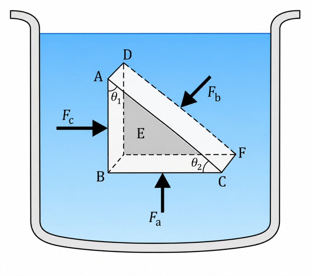
In the above figure, ABC-DEF is an element of the interior of a fluid at rest. This element is in the form of a right angled prism. The element is small so that the effect of gravity can be ignored, but it has been enlarged for the sake of clarity.
Figure shows an element in the interior of a fluid at rest. This element ABC-DEF is in the form of a right-angled prism. In principle, this prismatic element is very small so that every part of it can be considered at the same depth from the liquid surface and therefore, the effect of the gravity is the same at all these points. But, for clarity, we have enlarged this element. The forces on this element are those exerted by the rest of the fluid and they must be normal to the surfaces of the element as discussed above. Thus, the fluid exerts pressures Pₐ, Pb and P𝑐 on this element of area corresponding to the normal forces Fₐ, Fb and Fc as shown in figure on the faces BEFC, ADFC and ADEB denoted by Aₐ, Ab and Ac respectively. Then,
Fb sinθ2 = Fc , Fb cosθ2 = Fₐ
(by equilibrium)
Ab sinθ2 = Fc , Ab cosθ2 = Aₐ
(by geometry)
Thus,
Fb / Ab = Fc / Ac = Fₐ / Aₐ
Pb = Pc= Pₐ
Hence, pressure exerted is same in all directions in a fluid at rest.
It again reminds us that like other types of stress, pressure is not a vector quantity. No direction can be assigned to it. The force against any area within (or bounding) a fluid at rest and under pressure is normal to the area, regardless of the orientation of the area.
Now consider a fluid element in the form of a horizontal bar of uniform cross-section. The bar is in equilibrium. The horizontal forces exerted at its two ends must be balanced or the pressure at the two ends should be equal. This proves that for a liquid in equilibrium the pressure is same at all points in a horizontal plane. Suppose the pressure were not equal in different parts of the fluid, then there would be a flow as the fluid will have some net force acting on it. Hence in the absence of flow the pressure in the fluid must be same everywhere. Wind is flow of air due to pressure differences.
Variation of Pressure with Depth in a Static Fluid:
Consider a liquid of density ρ contained in a vessel I shown in figure. Let us find the pressure difference between two points P and Q separated by a vertical distance h.
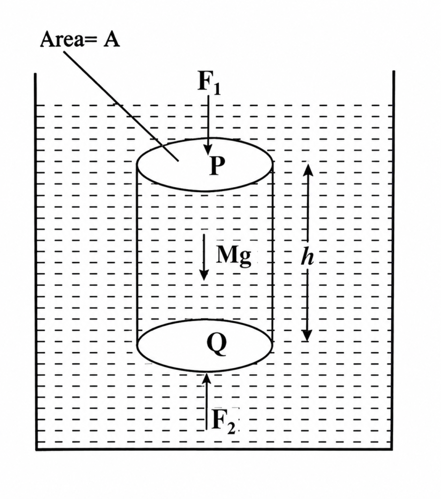
In order to calculate the pressure difference between points P and Q, consider an imaginary cylinder of liquid of cross sectional area A, such that points P and Q lie on its upper and lower circular faces respectively. Obviously, the length of the cylinder will be h and it will contain liquid, whose weight is given by
Mg = Volume × Density × g
Mg = (Ah)ρg
The weight of the liquid of the imaginary cylinder act vertically downwards. Let P1 and P2 be values of pressure at points P and Q respectively.
Now, force on the upper face of the cylinder, F1 = P1A ( Vertically Downwards)
Therefore total force on the cylinder,
= F1 + Mg (Vertically Downwards)
Also force on the lower face of the cylinder,
F2 = P2A ( Vertically Upwards)
Since the imaginary cylinder of the liquid is in equilibrium, the net force on it must be zero i.e.
(F1 + Mg) – F2 = 0
Substituting for F1, F2 and Mg, we have
(P1A+Ahρg) – P2A=0
P2 – P1 = hρg ———> (1)
This equation gives the difference of pressure between the points P and Q when the effect of gravity is considered.
If the effect of gravity is neglected (i.e. weight of the imaginary cylinder of the liquid is neglected), then
P2 – P1 = 0
From equation (1), we conclude the following,
i) when the point P lies at the surface of the liquid and the point Q is at a depth h below it, then pressure at P is
P1 = P0 ( P0 is atmospheric pressure)
Pressure at Q is
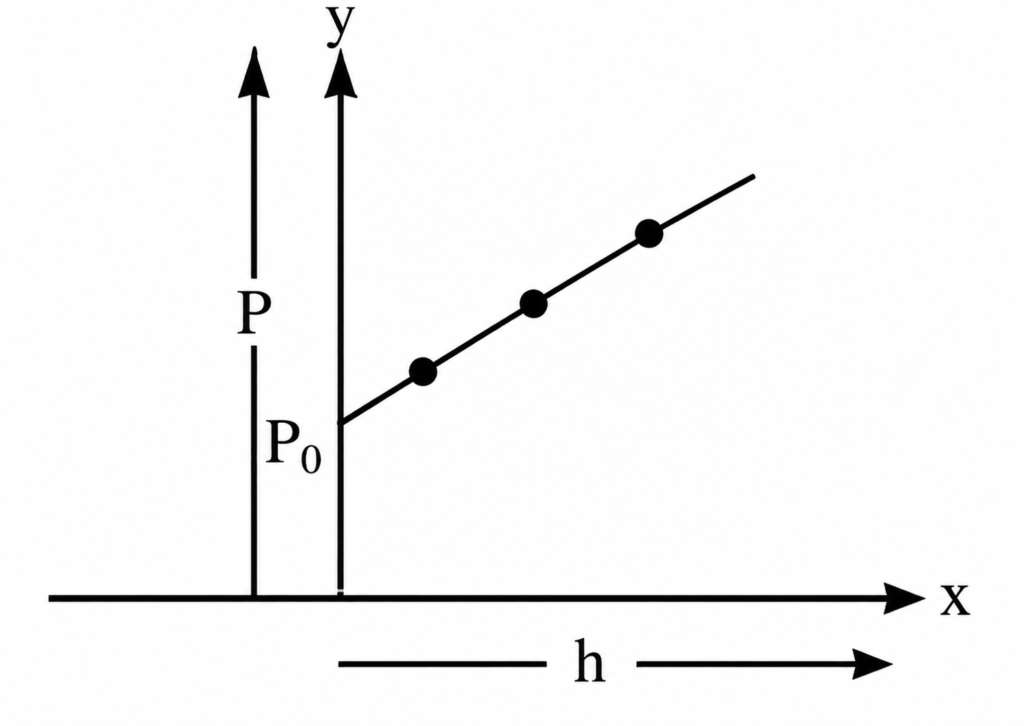
P2 = P0 + hρg
The difference of pressure between any two points located vertically one above the other inside the liquid is because of the effect of gravity. In the absence of gravity, no such pressure difference exists between different points inside the liquid.
The graph represents change of hydrostatic pressure with depth.
What is Atmospheric Pressure and Barometer?
“The pressure exerted by the atmosphere on the upper surface of the earth is called atmospheric pressure“. All the objects that are present within the atmosphere get exerted by the atmospheric pressure.
Expression for Atmospheric Pressure:
The atmosphere of the earth is spread upto a height of about 200 km. This atmosphere presses the bodies on the surface of the earth. The force exerted by the air on any body is perpendicular to the surface of the body.
Barometer is a device used to measure the atmospheric pressure.
In this, a glass tube open at one end and having a length of about a meter is filled with mercury. The open end is temporarily closed (by a thumb) and the tube is inverted in a cup of mercury. With the open end dipped into the cup, the temporary closure is removed.
The mercury column in the tube falls down a little and finally stays at some position as shown in figure.
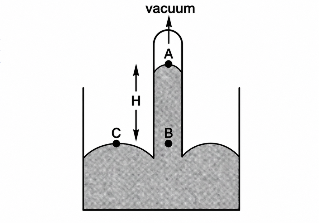
The upper part of the tube contains vacuum as the mercury goes down and no air is allowed inside. The pressure at the upper end A of the mercury column inside the tube is Pₐ = zero. Let us consider a point C on the mercury surface in the cup and another point B in the tube at the same horizontal level of C.
The pressures at B and C are equal. Suppose the point B is at a depth H below A and ρ be the density of mercury,
the atmospheric pressure is also represented in terms of height of Mercury column in a barometer the height of Mercury column in barometer is about 76 cm.
∴ 1 atm = 76 cm of Hg (pressure exerted by mercury column of height 76 cm at its bottom)
MANOMETER
Manometer is a simple device to measure the pressure in a closed vessel containing a gas. It consists of a U-tube having some liquid. One end of the tube is open to the atmosphere and the other end is connected to the vessel (figure).
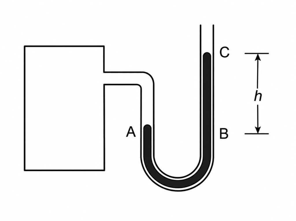
The pressure of the gas is equal to the pressure at A
= pressure at B
= pressure at C + hρg
= P₀ + hρg
when P₀ is the atmospheric pressure, h=BC is the difference in levels of the liquid in the two arms and ρ is the density of the liquid.
The excess pressure P − P₀ is called the gauge pressure.
WHAT ARE HYDRAULIC MACHINES :
Hydraulic machines are devices that use the pressure transmitted through a liquid to multiply force or transmit force from one place to another. They work mainly on Pascal’s law.
“Pascal’s law states that, when pressure is applied to a confined incompressible liquid, the pressure is transmitted equally and undiminished in all directions throughout the liquid and to the walls of its container.This principle is the basis of hydraulic machines”.
Principle of Hydraulic Machine:
Consider two cylinders connected by a tube and filled with an incompressible liquid such as hydraulic oil.
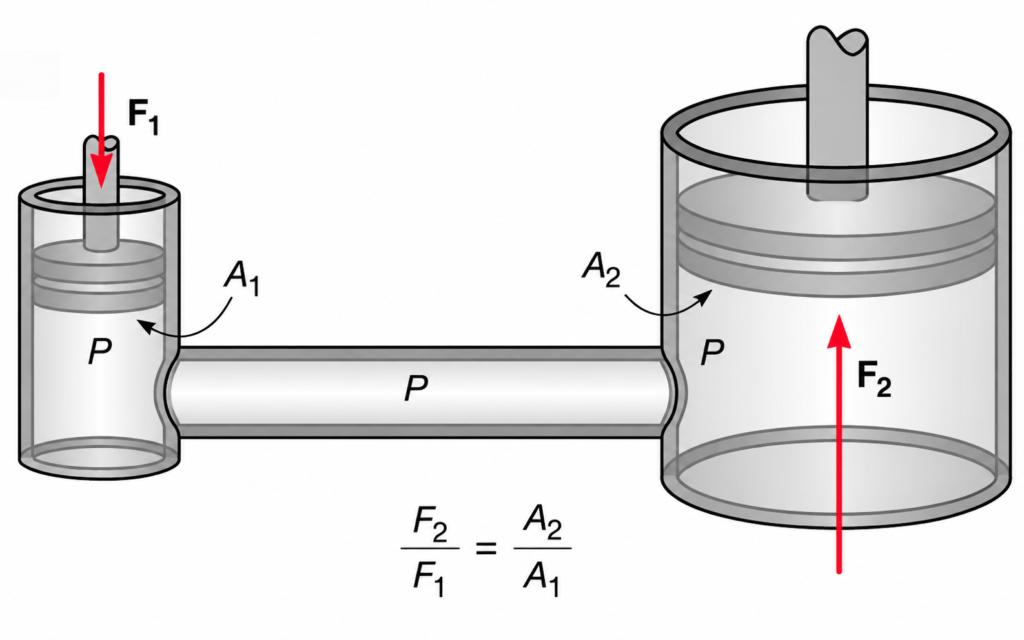
- A1 = area of the smaller piston
- A2 = area of the larger piston
- F1 = force applied on the smaller piston
- F2 = force produced by the larger piston
The pressure produced on the liquid by the smaller piston is equal to force divided by the area over which the force acts.
According to Pascal’s law, this pressure is transmitted equally through the liquid to the larger piston.
Therefore, the pressure acting on the larger piston is:
Since the pressure is transmitted equally,
Rearranging this equation, we obtain
This is the fundamental equation of a hydraulic machine.
It shows that the output force F2 can be much larger than the input force F1 when the area of the larger piston is much greater than the area of the smaller piston.
Applications of Hydraulic Machine:
1. Hydraulic Lift :
A hydraulic lift is an important application of Pascal’s law. It is used to lift heavy objects with the help of a relatively small force. Hydraulic lifts are commonly found in automobile service stations and workshops, where they are used to raise cars and other heavy vehicles.
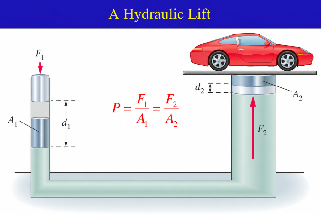
Construction of Hydraulic Lift:
A hydraulic lift consists of,
- A small cylinder containing a small piston.
- A large cylinder containing a large piston.
- A connecting pipe between the two cylinders.
- An incompressible hydraulic liquid.
- A platform on the large piston to support the load.
Working of Hydraulic Lift:
When a downward force F1 is applied to the small piston of area A1, pressure is produced in the liquid.
According to Pascal’s law, this pressure is transmitted equally to the large piston. The pressure acting on the large piston is:
Since the pressure is transmitted equally,
Therefore,
If A2 is much greater than A1, then F2 is much greater than F1. The large piston therefore rises and lifts the heavy load placed on it.
Example:
Suppose,
and
Then,
Therefore,
Thus, an applied force of 2,000 N can ideally produce an upward force of 10,000 N.
Hydraulic Brakes :
Hydraulic brakes are another important application of Pascal’s law. They are widely used in automobiles such as cars and motorcycles.
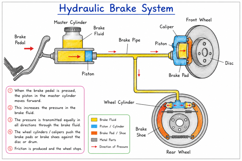
A hydraulic braking system generally consists of:
- Brake pedal
- Master cylinder
- Master-cylinder piston
- Brake fluid
- Brake pipes
- Wheel cylinder or brake caliper
- Brake pads or brake shoes
- Brake disc or drum
Working of Hydraulic Brakes:
When the driver presses the brake pedal, the pedal pushes a piston inside the master cylinder.
Suppose the force applied to the master-cylinder piston is F1, and the area of this piston is A1.
The pressure produced in the brake fluid is:
Brake fluid is nearly incompressible. Therefore, the pressure is transmitted through the brake pipes to the wheel cylinders or brake calipers.
If the effective area of the wheel-cylinder piston is A2, and the force produced there is F2, then:
According to Pascal’s Law,
Therefore,
and hence,
The force produced at the wheel cylinder or brake caliper pushes the brake pads against the rotating brake disc, or the brake shoes against the brake drum.
The frictional force between the brake pads and the disc opposes the rotation of the wheel. As a result, the vehicle slows down and eventually stops.
Other Applications of Hydraulic Machines :
Hydraulic Jack
A hydraulic jack uses Pascal’s law to raise heavy vehicles. A relatively small force applied to the small piston produces a large lifting force on the large piston.
Hydraulic Press
A hydraulic press is used to compress, shape, mould or form materials. It is widely used in industrial applications.
Hydraulic Excavator :
Hydraulic excavators use hydraulic cylinders to move the boom, arm and bucket. Hydraulic pressure allows the machine to produce very large forces.
Hydraulic Crane
Hydraulic systems are used in cranes to lift and move heavy loads.
Hydraulic Power Steering
Hydraulic power steering systems use fluid pressure to assist the driver in turning the wheels.
What is a Force of Buoyancy or Buoyant Force?
Buoyant force is the upward force exerted by a fluid on an object that is partially or completely immersed in it.
When an object is partially or completely immersed in a fluid, the fluid exerts forces on the object.
The pressure of a fluid increases with depth. Therefore, the pressure acting on the lower surface of an immersed object is greater than the pressure acting on its upper surface.
As a result, there is a net upward force acting on the object. This upward force exerted by the fluid is called the buoyant force or upthrust.
Why does Buoyant force act upwards?
Consider a rectangular object completely immersed in water.
The water exerts pressure on all surfaces of the object.
The pressure acting on the top surface produces a downward force, while the pressure acting on the bottom surface produces an upward force.
Because the bottom surface is at a greater depth, the pressure at the bottom is greater.
Therefore,
upward force on the bottom > downward force on the top.
The difference between these forces produces a net upward force, which is the buoyant force.
Derivation of the Buoyant Force:
Consider a rectangular object of height h and cross-sectional area A completely immersed in a liquid.
Let the depth of the top surface below the liquid surface be h1.
The pressure at the top surface is:
The pressure at the bottom surface is at a greater depth h2.
Therefore, the pressure at the bottom is:
Since h2 > h1,
The force exerted by a fluid pressure on an area A is:
Therefore, the downward force acting on the top surface is:
The upward force acting on the bottom surface is,
Hence, the net upward force is,
Substituting the expressions for F1 and F2,
Now substitute the pressure expressions,
But,
where V is the volume of the immersed portion of the object. Therefore,
The product ρV represents the mass of the displaced liquid:
Therefore,
But ‘mg’ is the weight of the displaced liquid. Hence,
Buoyant Force = Weight of Displaced fluid.
Archimedes Principle
Archimedes principle states that, when a body is partially or completely immersed in a fluid, it experiences an upward buoyant force equal to the weight of the fluid displaced by the body.
If the volume of liquid displaced is V, and the density of the liquid is ρ, then the mass of the displaced liquid is:
Therefore, it’s weight is
Hence, according to Archimede’s principle:
This is one of the most important equations associated with buoyancy.
When does a body float or sink or remain at neutral equilibrium?
Whether an object floats or sinks depends on the relationship between its weight and buoyant force.
Let the weight of the object be W.
The weight of the object is:
Case 1 : If Buoyant force is greater than weight.
the net force is upward.
Therefore, the object moves upward toward the surface.
Case 2: If Buoyant force is less than weight.
the net force is downward. Therefore, the object sinks.
Case 3: If Buoyant force equals weight.
the upward and downward forces balance each other. The object is in equilibrium.
For a floating object at rest,
Therefore,
This explains why a floating object displaces exactly enough liquid so that the weight of the displaced liquid equals the weight of the object.
Why does a heavy ship float?
This is an interesting application of buoyancy.
A ship is made mainly of materials such as steel, which are denser than water. However, the ship is hollow and contains a large volume of air.
Because of its hollow shape, the ship displaces a large volume of water.
The buoyant force is:
As the ship sinks slightly into the water, it displaces more water and therefore experiences a greater buoyant force.
The ship floats when:
Thus, even a very heavy ship can float if its shape allows it to displace enough water.
Why does a stone sink?
Consider a stone placed in water.
The stone has a relatively high average density compared with water.
When it is completely immersed, the maximum buoyant force it can receive is:
If the weight of the stone is greater than this buoyant force,
there is a net downward force.
Therefore, the stone sinks.
Apparent Weight in a Liquid:
When an object is immersed in a liquid, its apparent weight becomes less than its actual weight because the liquid provides an upward buoyant force.
Let,
- W = actual weight of the object
- Wapp = apparent weight
- FB = buoyant force
- The forces acting on the object are:
- Weight W, downward
- Buoyant force FB, upward
Therefore, the apparent weight is:
Hence,
So, the loss of weight of an object when immersed in a fluid is equal to the buoyant force acting on it.
Applications of Buoyancy:
Buoyancy has many important applications in everyday life and science.
Ships and boats:
Ships float because their hollow structures allow them to displace a large volume of water.
Submarines:
Submarines control their buoyancy by taking water into or expelling water from their ballast tanks.
Life jackets:
Life jackets contain materials or air-filled chambers that increase the volume of the person-plus-jacket system without greatly increasing its mass. This increases the buoyant force and helps the person remain afloat.
Hydrometers:
A hydrometer is an instrument used to measure the relative density or specific gravity of liquids. It floats at different depths depending on the density of the liquid.
Hot-air balloons:
The principle of buoyancy also applies to gases. A hot-air balloon rises when the buoyant force exerted by the surrounding air is greater than the total weight of the balloon and its contents.
WHAT IS BERNOULLI’S PRINCIPLE?
Bernoulli’s principle states that for the steady flow of an ideal fluid, the sum of pressure energy per unit volume, kinetic energy per unit volume and gravitational potential energy per unit volume remains constant along a streamline.
In simple words:
When a fluid flows steadily, an increase in its speed is generally accompanied by a decrease in its pressure, provided the height remains the same.
We have already seen that a fluid can exert pressure on objects and that pressure plays an important role in hydraulic machines and buoyancy.
Now let us consider a moving fluid.
When a fluid flows through a pipe, its speed need not be the same everywhere. For example, when water flows through a pipe that becomes narrower, the water flows faster through the narrow portion.
This leads to an important relationship between pressure, speed and height of a flowing fluid. This relationship is known as Bernoulli’s principle.
Bernoulli’s Equation :
Consider a fluid flowing through a pipe whose cross-sectional area changes from one point to another.
Let the fluid have:
- Pressure P1, speed v1, and height h1 at point 1.
- Pressure P2, speed v2, and height h2 at point 2.
For an ideal fluid, the total mechanical energy per unit volume remains constant.
Therefore,
This is the Bernoulli equation.
It can also be written as:
Where,
- P = pressure of the fluid
- ρ = density of the fluid
- v = speed of the fluid
- g = acceleration due to gravity
- h = height of the fluid above a chosen reference level
Derivation of Bernoulli’s Equation using Work-Energy Theorem:
Consider an ideal fluid flowing steadily through a pipe of varying cross-sectional area.
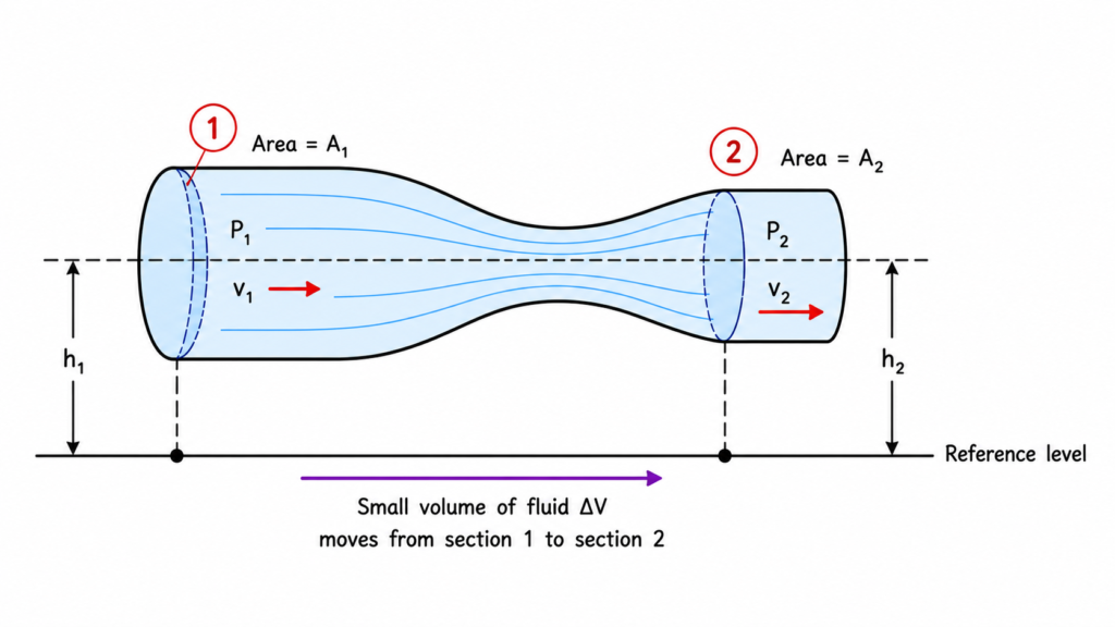
Take two points, 1 and 2, along the same streamline.
At point 1:
- Pressure = P1
- Velocity = v1
- Height = h1
- Cross-sectional area = A1
At point 2:
- Pressure = P2
- Velocity = v2
- Height = h2
- Cross-sectional area = A2
Let a small volume of fluid ΔV move from point 1 to point 2.
The mass of this fluid is:
where ρ is the density of the fluid.
Work done by the pressure forces:
At point 1, the pressure P1 pushes the fluid forward. Therefore, the work done by this pressure is:
At point 2, the pressure P2 opposes the motion of the fluid. Therefore, the work done against this pressure is:
Hence, the net work done by the pressure forces is:
Therefore,
Apply the Work-Energy Theorem:
According to the work-energy theorem:
The net work done on a body is equal to the change in its kinetic energy.
The fluid changes its speed from v1 to v2.
Therefore, the change in kinetic energy is:
Substititing,
We get,
But the fluid also changes its height from h1 to h2. Therefore, its gravitational potential energy changes.
The change in gravitational potential energy is:
Substituting m=ρΔV:
Therefore, the work done by the pressure forces produces both:
- Change in kinetic energy
- Change in gravitational potential energy
Hence, by the work-energy theorem:
Divide both sides by ΔV,
Expanding the right hand side,
Now, by rearranging the terms:
Therefore,
This is Bernoulli’s equation.
Conditions for Bernoulli’s Equation:
Bernoulli’s equation is not applicable to every possible fluid flow. It is derived under certain ideal conditions.
The fluid should be:
1. Incompressible:
The density of the fluid should remain approximately constant.
2. Non-viscous:
The effect of viscosity and frictional energy loss is neglected.
3. Steady-flowing:
The fluid velocity at a particular point does not change with time.
4. Along a streamline:
The standard Bernoulli equation is applied along a streamline.
5. No external energy input or removal:
There should be no pump or turbine adding or removing mechanical energy between the two points in the basic form of the equation.
Applications of Bernoulli’s Principle :
1. Speed of Efflux Torricelli’s Law
2. Venturimeter
3. Pitot’s Tube
4. Blood Flow and Heart Attack
5. Dynamic Lift
(a) Lift on Aircraft Wing
(b) Blowing off of Roofs by Wind Storms
(c) Attraction between two parallel and
closely moving boats.
(d) Magnus Effect
SPEED OF EFFLUX TORRICELLI’S LAW
The word efflux means fluid outflow. Torricelli discovered that the speed of efflux from an open tank is given by a formula identical to that of a freely falling body. Consider a tank containing a liquid of density r with a small hole in its side at a height y1 from the bottom (sec Fig. ) The air above the liquid, whose surface is at height y2 is at pressure P. From the equation of continuity, we have
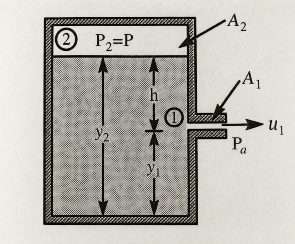
If the cross sectional area of the tank A₂ is much larger than that of the hole (A₂ >> A₁), then we may take the fluid to be approximately at rest at the top, i.e. u₂ = 0. Now applying the Bernoulli’s equation at point 1 and 2 and noting that at the hole P₁ = Pₐ(the atmospheric pressure),
When P>>Pa and 2gh may be ignored, the speed of efflux is determined by the container pressure. Such a situation occurs in rocket propulsion.On the other hand if the tank is open to the atmosphere, then P = Pa and
This is the speed of a freely falling body. The above equation is known as Torricelli’s law.
Horizontal range of Efflux (X):
when air drag is neglected on the water coming out of the hole, it will follow a parabolic path with a constant horizontal speed of,
the time taken by the water to reach the ground is,
The horizontal range of water on striking the ground is
substituting the values of v and t in the above expression of x, we have
VENTURIMETER
Venturimeter is a device used for measuring the speed of incompressible liquid and rate of flow of liquid through pipes. Its working is based on Bernoulli’s Theorem.
Construction :
It consists of two identical coaxial wide tubes A and C connected by a narrow coaxial tube B. A manometer in the form of U tube is attached to it, with one arm at the wider neck point of the tube A and the other arm at the narrow middle point to the tube B, as shown in Fig. Low density liquid is used in manometer which may not mix with the liquid flowing in the tubes of venturimeter.
Working and Theory :
Connect this venturimeter horizontally to the pipe through which the liquid is flowing with steady flow. Note down the difference of liquid column in two arms of U tube. Let it be h.
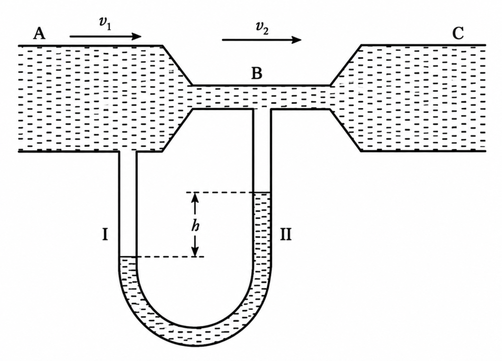
Let ρ be density of liquid flowing through the pipe.
ρₘ be density of liquid in U tube.
a₁, a₂ be areas of cross-section of tubes A and B respectively.
v₁, v₂ be velocities of liquid flow through A and B respectively.
P₁, P₂ be pressures at A and B respectively.
Let V be the volume of the liquid flowing per second (i.e. rate of flow of liquid) through the pipe.
According to equation of continuity,
Using Bernoulli’s equation for horizontal flow of liquid,
This pressure difference cause the liquid in the arm II of U-tube connected at the narrow tube B to rise in comparison to other arm I. The difference in height h of two arms of U-tube measures the pressure difference.
From (1) and (2), we have
It is the expression for speed of the liquid in the wide tube.
Volume of the liquid flowing per second through the wider tube is,
PITOT’S TUBE
A Pitot’s tube is a simple device which is used to measure the velocity of flow in the river. The basic principle used in the device is that if the velocity of flow at a particular point is reduced to zero, which is known a stagnation point, the pressure there is increased due to conversion of kinetic energy into pressure energy. By measuring pressure head, we can calculate velocity of flow.
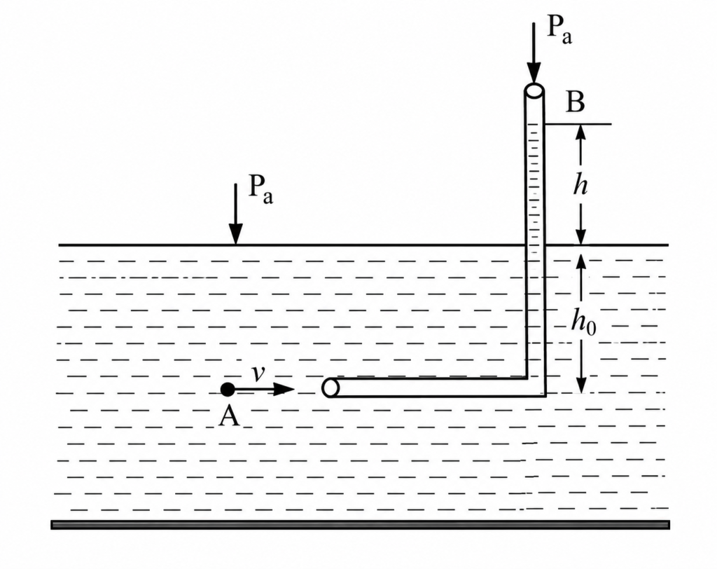
Consider two points A and B as shown. Using Bernoulli’s Equation between these points,
Explanation of Blood Flow and Heart Attack using Bernoulli’s Principle:
Bernoulli’s principle helps in explaining blood flow in artery. The artery may get constricted due to the accumulation of plaque on its inner walls. In order to drive the blood through this constriction a greater demand is placed on the activity of the heart.
The speed of the flow of the blood in this region is raised which lowers the pressure inside and the artery may collapse due to the external pressure. The heart exerts further pressure to open this artery and forces the blood through. As the blood rushes through the opening, the internal pressure once again drops due to same reasons leading to a repeat collapse. This may result in heart attack.
The gauge pressure in an air sack wrapped around the upper arm is measured using a manometer or a dial pressure gauge (Fig.). The pressure in the sack is first increased till the brachial artery is closed. The pressure in the sack is then slowly reduced while a stethoscope placed just below the sack is use to listen to noises arising in the brachial artery.
When the pressure is just below the systolic (peak) pressure, the artery opens briefly. During this brief period, the blood velocity in the highly constricted artery is high and turbulent and hence noisy. The resulting noise is heard as a tapping sound on the stethoscope.
When the pressure in the sack is lowered further, the artery remains open for a longer portion of the heart cycle. Nevertheless, it remains closed during the diastolic (minimum pressure) phase of the heartbeat. Thus the duration of the tapping sound is longer.
When the pressure in the sack reaches the diastolic pressure the artery is open during the entire heart cycle. The flow is however, still turbulent and noisy. But instead of a tapping sound we hear a steady, continuous roar on the stethoscope.
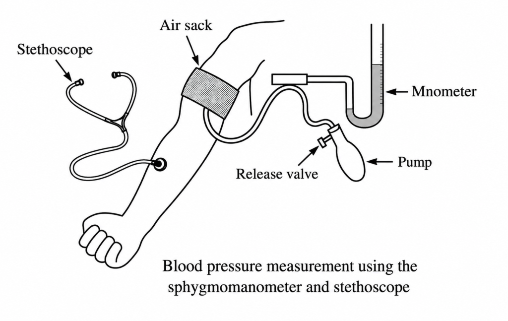
The blood pressure of a patient is presented as the ratio of systolic/ diastolic pressures. For a resting healthy adult it is typically 120/80 mm of Hg (120/80) torr. Pressures above 140/90 require medical attention and advice. High blood pressures may seriously damage the heart, kidney and other organs and must be controlled.
Explanation of Lift on Aircraft Wing using Bernoulli’s principle :
An aircraft wing (also called an air foil) has a cross-sectional shape as shown. It has a concave shape at the bottom. When the aeroplane flies at a great speed or when the fluid (air) flows past the airfoil, the flow is divided into two streams due to the asymmetrical shape. The velocity of fluid flow at the top surface of the wing (v₁) will be greater than the velocity of fluid flow (v₂) at the bottom. Due to this, pressure at the top of the air foil (P₁) is correspondingly less than the pressure at the bottom of the air foil (P₂). Then due to Bernoulli’s Principle this difference in pressure will produce dynamic lift.
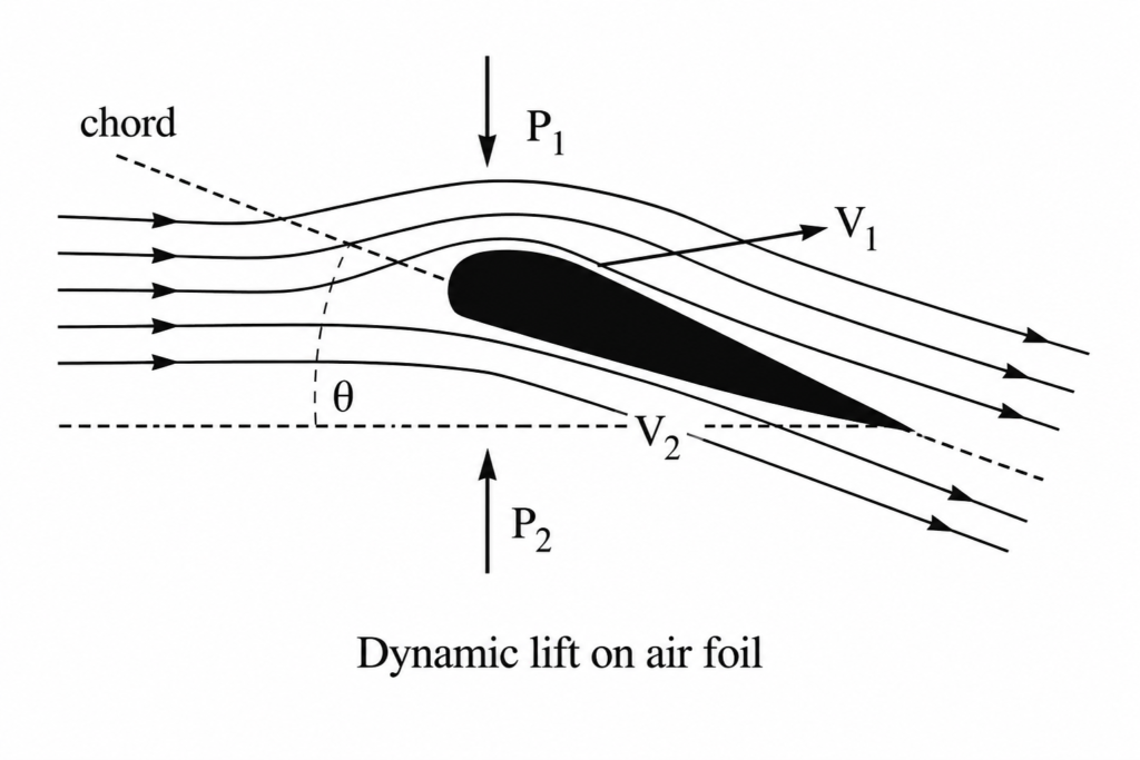
The wing shape shown creates an air-resistance due to flow called dynamic drag, on the aeroplane. Hence it is used in low speed aircraft.The angle between the chord of the airfoil and the wind stream direction is known as the angle of attack. Its value does not exceed 3° to 4° for modern air planes.
According to Bernoulli’s Theorem,
Aerodynamic lift = Pressure difference × Area of the wings
Explanation for why roofs blow off by wind storms :
During a wind storm, when a high speed wind blows over a roof, it creates a lower pressure over the roof pressure P₀. So, due to this difference of pressure, the roof is lifted up and is then blown off by the wind.
Explanation for why two parallel and closely moving boats attract each other:
When two boats move side by side in the same direction, water in the region between them moves faster than that on the remote sides. Consequently, in accordance with Bernoulli’s equation the pressure between the boats is reduced and hence due to higher pressure outside, they are pushed towards each other. Similarly, keeping two sheets of paper parallel to each other, when air is blown between the sheets, they attract towards each other.
Magnus Effect :
When a spinning ball is thrown, it deviates from its usual path in flight. This effect is called Magnus effect.
It plays an important role in tennis, cricket, soccer etc. By applying appropriate spin, the moving ball can be made to curve in any desired direction.
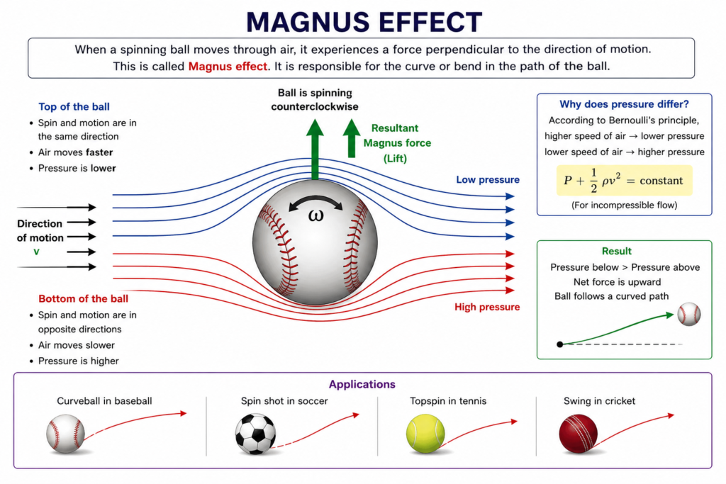
Consider a ball moving in a fluid (air) without spin. If we take frame of reference with respect to the center of mass of the ball, the stream lines of air at the top and at the bottom of the ball are symmetric. The speed of air at points equidistant above and below the centre of the ball are same. So, pressure at corresponding points is same and no lift acts on the ball.
If a ball is moving from left to right and is also spinning about a horizontal axis perpendicular to the direction of motion as shown in figure, different points in sphere will have different speeds.
For example the highest point of the sphere has a speed of v+rω and the lowest point has the speed of v-rω as shown in figure. Due to viscous effects, the air layer in contact with the sphere will also be dragged along with it. As a result, speed of air just above the sphere is (v + rω) and that just below the sphere is (v − rω). Neglecting viscous forces in air (viscosity of air is very small) and also neglecting the variations of gravitational potential energy of air across the sphere (density of air is very small).
We can apply Bernoulli’s equation to top and the bottom of the sphere,
Due to the difference in pressure across the sphere, there is a net upward pressure force, in addition to gravitational force. As a result, the trajectory is less curved as compared with that when only gravity is present.
similarly if the spin is given clock wise, the force due to pressure difference also act downwards, along with the gravity and so the path will curve more sharply shortening the flight.
What is Aerodynamic Lift?
The lift or upthrust experienced by an object during its motion in a fluid is called dynamic lift. If the object moves in air this dynamic lift is called aerodynamic lift.
Other Real-Life Examples of Bernoulli’s Principle:
Bernoulli’s principle has many important applications in everyday life and technology.
Some important examples are:
2. Atomizer and perfume sprayer
3. Lift on an airplane wing
4. Flow of liquid from a tank
5. Chimney
6. Roof lifting during strong winds
7. Carburetor
Let us understand the important ones.
Atomizer or Perfume Sprayer:
An atomizer is another simple application of Bernoulli’s principle.
When air is blown rapidly across the upper end of a narrow tube, the speed of air increases.
According to Bernoulli’s principle, the pressure at that region decreases.
The pressure of the liquid in the bottle is then greater than the pressure above the tube.
As a result, the liquid rises through the tube and is carried away by the fast-moving air as tiny droplets.
This is why perfume sprayers and some types of spray devices work using the pressure difference produced by rapidly moving air.
Lift on an Airplane Wing:
The shape of an airplane wing is designed so that air flows differently over its upper and lower surfaces.
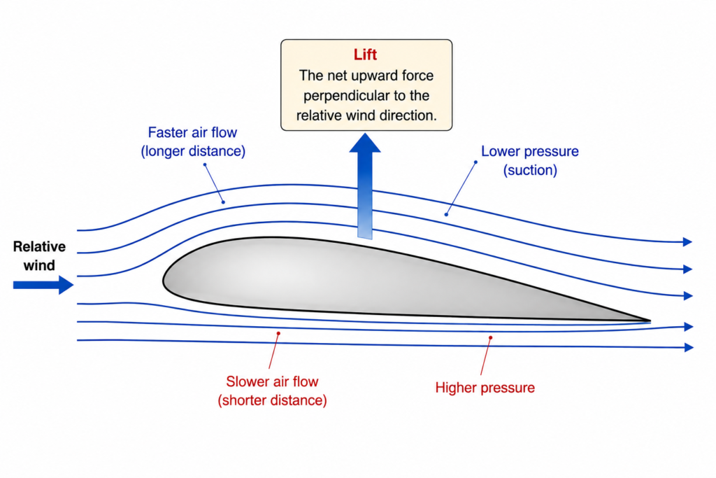
In the simplified Bernoulli explanation, air moves faster over one surface of the wing than the other.
If the velocity above the wing is greater,
then Bernoulli’s principle indicates a lower pressure in the region of greater velocity:
The resulting pressure difference contributes to an upward force called lift.
Important note:
For a scientifically complete explanation of aircraft lift, Bernoulli’s principle should not be treated as the only explanation. The pressure distribution around the wing is connected to the wing’s shape, angle of attack and the way the wing changes the momentum of the surrounding air.
Flow of Liquid from a Tank:
Consider a tank containing liquid with a small opening near its bottom.
The liquid flows out through the opening because of the pressure difference produced by the height of the liquid column.
Bernoulli’s equation can be used to determine the speed of efflux.
If the surface of the liquid and the opening are at heights h1 and h2, respectively, Bernoulli’s equation is:
If both points are exposed to atmospheric pressure:
If the tank is very large compared with the opening, the speed of the liquid surface is approximately zero:
Therefore, the speed of efflux is approximately:
This result is known as Torricelli’s law.
Chimney Effect :
The chimney of a house or industrial furnace allows smoke and hot gases to escape.
Hot gases inside the chimney are less dense and rise upward. The movement of air and gases involves pressure differences and fluid-flow principles.
Bernoulli’s principle can contribute to understanding pressure changes associated with moving gases, although the complete chimney effect also involves buoyancy and convection.
Roofs Can Be Lifted During Strong Winds:
During a strong wind, air moves rapidly over the roof of a building.
The rapidly moving air can have a lower pressure than the relatively still air inside the building.
Therefore, a pressure difference may develop between the inside and outside of the building.
If the pressure difference becomes sufficiently large, it can produce an upward force on the roof.
This is one reason why strong storms can damage roofs.
EQUATION OF CONTINUITY
Equation of continuity is a mathematical expression which defines that when a fluid flows through a pipe, the amount of fluid passing through different sections of the pipe depends on the cross-sectional area and the velocity of the fluid.
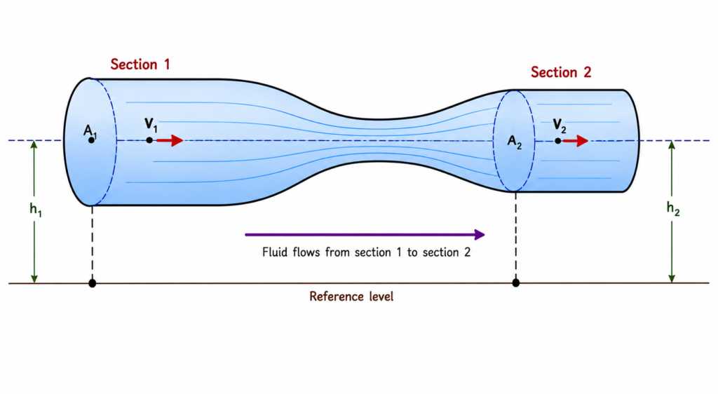
Consider a fluid flowing through a pipe whose cross-sectional area is different at different points.
Let the area of the pipe at one point be A1, and at another point be A2. Let the velocities of the fluid at these points be v1 and v2, respectively.
If the fluid flow is steady, the fluid flowing through any section does not change with time. If the fluid is incompressible, its density remains constant. Therefore, the same amount of fluid must pass through every cross-section of the pipe in a given time.
When the pipe becomes narrower, a smaller cross-sectional area is available for the fluid to pass through. To maintain the same flow, the fluid must move faster through the narrower section. Similarly, when the pipe becomes wider, the fluid moves more slowly. Thus, the velocity of an incompressible fluid is inversely related to the cross-sectional area of the pipe.
This relationship is a consequence of the law of conservation of mass.
In other words, fluid cannot simply disappear or accumulate inside the pipe during steady flow. The mass entering a section of the pipe per second must equal the mass leaving it per second. Therefore, the product of cross-sectional area and velocity remains constant for steady flow of an incompressible fluid.
This relationship is called the equation of continuity. It is one of the fundamental equations used to study the motion of fluids.
It is particularly useful when the cross-sectional area of a pipe changes. The equation of continuity also helps us understand why water flows faster through a narrow portion of a pipe. It forms an important basis for understanding devices such as the Venturi meter.
Derivation of the Equation of Continuity:
Consider an incompressible fluid flowing steadily through a pipe of varying cross-sectional area.
Let the cross-sectional area and velocity of the fluid at section 1 be A1 and v1, respectively. At section 2, let them be A2 and v2, respectively.
Suppose the fluid flows for a time interval Δt.
During this time, the distance travelled by the fluid at section 1 is:
Therefore, the volume of fluid passing through section 1 is:
Similarly, during the same time interval, the distance travelled by the fluid at section 2 is:
Therefore, the volume of fluid passing through section 2 is:
Since the fluid is incompressible and the flow is steady, the same volume of fluid passes through both sections in the same time.
Therefore,
Substituting the expressions for the two volumes:
Therefore, this is the Equation of Continuity for an incompressible fluid.
Therefore, the product of cross-sectional area and velocity remains constant:
Applications of the Equation of Continuity
1. Flow of water through pipes:
The equation of continuity explains why water flows faster through a narrow section of a pipe.
If the pipe becomes narrower, its area decreases and the velocity of the water increases.
2. Garden hose:
When the opening of a garden hose is partially closed with a finger, the effective cross-sectional area of the opening decreases. Consequently, the water comes out with greater speed.
3. Venturimeter:
The equation of continuity is an important part of the working of a Venturimeter. A Venturimeter has a narrow section called the throat. The fluid moves faster through this narrow section.
The relationship is:
The equation of continuity is then used together with Bernoulli’s equation to determine the flow rate of the fluid.
4. Blood flow:
The principle can also help us understand how the velocity of blood changes when the cross-sectional area of blood vessels changes.
What is Streamline Flow?
The flow of a fluid is said to be steady, orderly, streamline or laminar, if every particle of the fluid follows exactly the path of its preceding particle and has the same velocity (both in magnitude and direction) as that of its preceding particle when crossing that point.
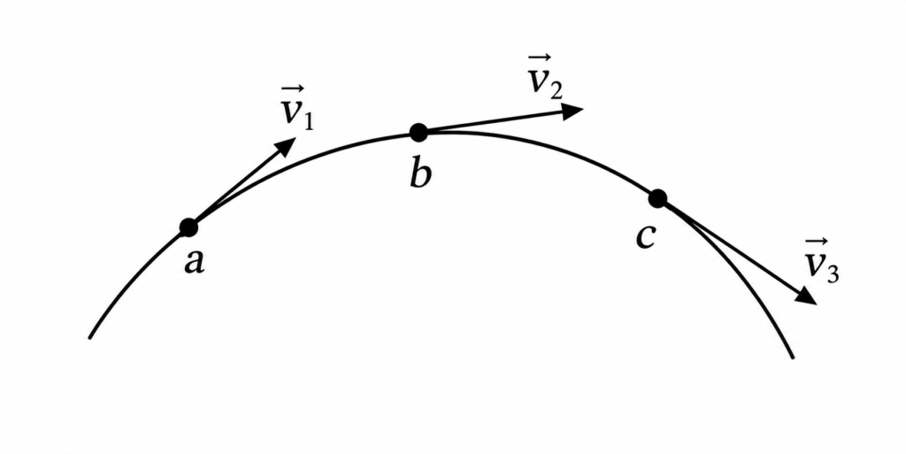
Explanation : Consider a liquid flowing along the path abc. Let v1, v2 and v3 be the velocities of a particle of the liquid at points a, b and c. If the flow of the liquid is streamlined, then each new particle of the liquid arriving at ‘a’ will have the same velocity v₁. This velocity is directed along the tangent to curve abc at the point ‘a’. A particle arriving at ‘b’ will always have the same velocity v₂. This velocity may or may not be equal to v₁. Similarly, a particle passing through ‘c’ will have the velocity v₃.The fixed path followed by an orderly procession of particles in the steady flow of a liquid is called streamline. In the above diagram the line abc represents a streamline.
A group of streamlines is called a tube of flow.
As the velocity vector at each point is tangent to a streamline, it will also be tangent to the surface of the tube of flow. The particles of the fluid do not intersect the walls of the tube of flow. Hence no flow is observed into or out of the sides of a tube of flow.
Properties:
i) The tangent at any point of the streamline gives the direction of velocity of the liquid at that point.
ii) Two streamlines cannot intersect. If two streamlines intersect, then it would mean two different directions of velocity at a given point. This is physically impossible. Hence two streamlines cannot intersect.
iii) The streamlines are closer where fluid velocity is higher, and are farther apart where velocity is lower.
iv) Streamlines may be either straight or curved, such that tangent to it at any point indicates the direction of the flow of the liquid at that point.
v) A streamline flow is not necessarily an ideal flow.
vi) A streamline flow is not necessarily an incompressible flow.
What is Turbulent flow?
The flow of a fluid is said to be unsteady, disorderly or turbulent, if every particle of the fluid does not follow exactly the path of its preceding particle and has the different velocity compared with its preceding particle when crossing that point.
An obstacle placed in the path of a fast moving fluid causes turbulence (Fig.).
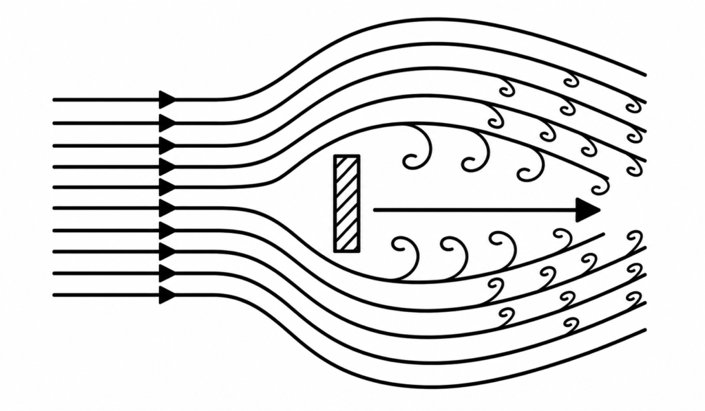
The smoke rising from a burning stack of wood, oceanic currents are turbulent. Twinkling of stars is the result of atmospheric turbulence. The waves in the water and in the air left by cars, aeroplanes and boats are also turbulent.
Examples of Turbulent Flow:
i) After rising a short distance, the smooth column of smoke from a cigarette breaks up into an irregular and random pattern.
ii) The moving cars and airplanes produce turbulent fluid flow.
iii) The sounds produced by whistling and by wind instruments result from the turbulent flow of air.
Note :
i) Streamline flow is characterised by viscosity and turbulent flow is characterised by density.
ii) In streamline flow, velocity of fluid is less than critical velocity and in turbulent flow, velocity of the fluid is more than the critical velocity.