● 1. Moment of Inertia of Thin Rod
● a) About an axis passing through the center of mass and perpendicular to its length
● b) About an axis passing through one end of the rod and perpendicular to its length
● 2. Moment of Inertia of a Circular Ring
● b) About a tangent in the perpendicular plane
● d) About a tangent in its plane
● 3. Moment of Inertia of a Circular Disc
● b) About a tangent perpendicular to its plane
● d) About a Tangent in its plane
● 4. Moment of Inertia of a Rectangular Lamina
● a) About an axis passing through its centre and perpendicular to its length
● b) About an axis passing through its centre and perpendicular to its breadth
● c) About an axis of rotation passing through its centre and perpendicular to its plane
● 5. Moment of Inertia of a Solid Sphere
● a) About an axis passing through its diameter
● b) About an axis passing through its tangent
● 6. Moment of Inertia of a Hollow Sphere
● a) About an axis passing through the diameter
● b) About an axis passing through its tangent
● 7. Moment of Inertia of a Solid Cylinder
● a) About its own axis, i.e., axis of symmetry
● b) About an axis perpendicular to its geometrical axis and passing through its centre
● 8. Moment of Inertia of a Hollow Cylinder
● b) About an Axis Perpendicular to Its Geometrical Axis and Passing Through Its Centre
● 9. Kinetic Energy of Rotating Body
● 11. Relation between Areal Velocity and Angular Acceleration
● 12. Relation between Torque and Angular Momentum
● 13. Law of Conservation of Angular Momentum
● i) Examples for Conservation of Angular Momentum
● 14. Work, Energy and Power for Rotating Body
● a) Velocity at any instantaneous point on the rolling body
● b) Velocities at different points on the rolling wheel
● 17. Kinetic Energy of Rolling Body
Moment of Inertia of Thin Rod
About an Axis Passing Through the Centre of Mass and Perpendicular to Its Length
Consider a thin uniform rod of length l and mass M. Let AB be the axis of rotation passing through its centre of mass C and perpendicular to the length of the rod.
Let the linear mass density of the rod be
Consider a small element of the rod of length dx, situated at a distance x from the centre of mass C.
The mass of this small element is
The moment of inertia of this small element about the axis AB is
Substituting the value of dm,
Therefore, the moment of inertia of the entire rod about the axis AB is
Since the axis passes through the centre of mass, the limits of integration extend from \[ -\frac{l}{2} \] to \[ +\frac{l}{2}. \]
Using
we obtain
Therefore,
Simplifying,
Hence, the moment of inertia of a thin uniform rod about an axis passing through its centre of mass and perpendicular to its length is
The radius of gyration K is related to the moment of inertia by
Substituting the value of I,
Therefore,
About an Axis Passing Through One End of the Rod and Perpendicular to Its Length
Let A’B’ be the axis of rotation passing through one end of the rod and perpendicular to its length.
We know that the moment of inertia of a thin uniform rod of length l and mass M about an axis passing through its centre of mass and perpendicular to its length is
The axis A’B’ is parallel to the axis AB passing through the centre of mass, and the perpendicular distance between the two axes is
Therefore, applying the Parallel Axis Theorem, the moment of inertia of the rod about the axis A’B’ is
Substituting \[ I_C=\frac{Ml^2}{12} \] and \[ r=\frac{l}{2}, \] we get
Therefore,
Taking \(Ml^2\) common,
Hence,
Thus, the moment of inertia of a thin uniform rod about an axis passing through one end of the rod and perpendicular to its length is
The radius of gyration about this axis is
Substituting \[ I=\frac{Ml^2}{3}, \] we obtain
Therefore,
Result
Moment of Inertia of a Circular Ring
About an axis passing through its center and perpendicular to its plane, or about a transverse axis
Consider a circular ring of mass M and radius R. Let the axis of rotation pass through the centre of the ring and be perpendicular to its plane.
Every particle of the circular ring is at the same perpendicular distance R from the axis of rotation.
Let a small element of the ring have mass dm. Its distance from the axis of rotation is R.
The moment of inertia of this small element about the given axis is
\[ dI=R^2\,dm \]
Therefore, the moment of inertia of the complete ring is
\[ I=\int dI \]
Substituting \(dI=R^2\,dm\),
\[ I=\int R^2\,dm \]
Since R is constant for every element of the ring,
\[ I=R^2\int dm \]
The total mass of the ring is
\[ \int dm=M \]
Hence,
\[ I=MR^2 \]
\[ \boxed{I=MR^2} \]
Thus, the moment of inertia of a circular ring about an axis passing through its centre and perpendicular to its plane, or about a transverse axis, is
\[ \boxed{I=MR^2} \]
The radius of gyration is given by
\[ K=\sqrt{\frac{I}{M}} \]
Substituting \(I=MR^2\),
\[ K=\sqrt{\frac{MR^2}{M}} \]
\[ \boxed{K=R} \]
About a tangent in the perpendicular plane
Consider a circular ring of mass M and radius R. Let Ic be the moment of inertia of the circular ring about an axis passing through its centre and perpendicular to its plane.
The moment of inertia of the circular ring about this axis is
Now consider a tangent to the circular ring in a plane perpendicular to the plane of the ring. Let this tangent be parallel to the axis passing through the centre of the ring.
The distance between the tangent and the parallel axis passing through the centre of mass is equal to the radius of the ring.
By the parallel axes theorem, the moment of inertia of the ring about the tangent is
Substituting \(I_c = MR^2\) and \(r = R\),
Therefore, the moment of inertia of a circular ring about a tangent in the perpendicular plane is
The radius of gyration is given by
Substituting \(I = 2MR^2\),
About a Diameter
The moment of inertia of a circular ring about any diameter is the same. Consider two diameters XX1 and YY1 of the circular ring. These two diameters are perpendicular to each other and intersect at the centre O.
Let the moment of inertia of the circular ring about the diameter XX1 be
Similarly, the moment of inertia of the circular ring about the diameter YY1 is
Since the circular ring is symmetrical about both diameters,
Consider an axis ZZ1 passing through the centre O and perpendicular to the plane of the ring. The moment of inertia of the circular ring about this axis is
By the perpendicular axes theorem, the sum of the moments of inertia about the two mutually perpendicular axes in the plane of the ring is equal to the moment of inertia about the axis perpendicular to the plane of the ring.
Substituting \(I_x = I_y = I\) and \(I_z = MR^2\),
Therefore,
Hence, the moment of inertia of a circular ring about any diameter is
The radius of gyration is given by
Substituting \(I = \dfrac{MR^2}{2}\),
Result:
\[ \boxed{K = \frac{R}{\sqrt{2}}} \]
About a Tangent in its Plane
The tangent in the plane of a circular ring is parallel to the diameter.
The moment of inertia of a circular ring about a diameter is
\[ I_d=\frac{MR^2}{2} \]
where \(M\) is the mass of the circular ring and \(R\) is its radius.
Consider a tangent \(A’B’\) to the circular ring in its plane, as shown in the figure. The tangent \(A’B’\) is parallel to the diameter \(AB\) of the ring.
The distance between the diameter \(AB\), passing through the centre of mass \(O\), and the tangent \(A’B’\) is equal to the radius of the ring. Therefore,
\[ r=R \]
By the parallel axes theorem, the moment of inertia of the circular ring about the tangent \(A’B’\) is
\[ I=I_{\mathrm{CM}}+Mr^2 \]
Here, \(I_{\mathrm{CM}}\) is the moment of inertia of the ring about the parallel axis \(AB\) passing through its centre of mass.
For a circular ring, the moment of inertia about a diameter is
\[ I_{\mathrm{CM}}=\frac{MR^2}{2} \]
Since the perpendicular distance between the two parallel axes is
\[ r=R \]
substituting these values in the parallel axes theorem,
\[ I=\frac{MR^2}{2}+MR^2 \]
Taking \(MR^2\) as the common factor,
\[ I=MR^2\left(\frac{1}{2}+1\right) \]
Therefore,
\[ \boxed{I=\frac{3MR^2}{2}} \]
Hence, the moment of inertia of a circular ring about a tangent in its plane is
\[ \boxed{I=\frac{3}{2}MR^2} \]
Radius of Gyration
The radius of gyration \(K\) is given by
\[ K=\sqrt{\frac{I}{M}} \]
Substituting \[ I=\frac{3MR^2}{2}, \] we get
\[ K=\sqrt{\frac{\frac{3MR^2}{2}}{M}} \]
\[ K=\sqrt{\frac{3R^2}{2}} \]
\[ \boxed{K=\sqrt{\frac{3}{2}}\,R} \]
Thus, the radius of gyration of a circular ring about a tangent in its plane is
\[ \boxed{K=\sqrt{\frac{3}{2}}\,R} \]
Moment of Inertia of a Circular Disc
About an Axis Passing through its Centre and Perpendicular to its Plane, or About a Transverse Axis
Consider a uniform thin circular disc of mass \(M\) and radius \(R\). We have to find its moment of inertia about an axis passing through its centre and perpendicular to its plane.
Let the axis through the centre of the disc and perpendicular to its plane be the axis of rotation.
To derive the expression for the moment of inertia, consider a circular element of radius \(r\) and thickness \(dr\), as shown in the figure.
The area of the circular element is
\[ dA=2\pi r\,dr \]
The area of the complete disc is
\[ A=\pi R^2 \]
Since the disc is uniform, its surface mass density is
\[ \sigma=\frac{M}{\pi R^2} \]
Therefore, the mass \(dm\) of the circular element is
\[ dm=\sigma\,dA \]
Substituting the values of \(\sigma\) and \(dA\),
\[ dm=\frac{M}{\pi R^2}(2\pi r\,dr) \]
Hence,
\[ dm=\frac{2Mr}{R^2}\,dr \]
The moment of inertia of this elemental ring about the central perpendicular axis is
\[ dI=r^2\,dm \]
Substituting the expression for \(dm\),
\[ dI=r^2\left(\frac{2Mr}{R^2}\,dr\right) \]
Therefore,
\[ dI=\frac{2M}{R^2}r^3\,dr \]
The total moment of inertia of the disc is obtained by integrating from \(r=0\) to \(r=R\):
\[ I=\int_0^R dI \]
Thus,
\[ I=\frac{2M}{R^2}\int_0^R r^3\,dr \]
Using
\[ \int r^3\,dr=\frac{r^4}{4} \]
we obtain
\[ I=\frac{2M}{R^2} \left[ \frac{r^4}{4} \right]_0^R \]
Therefore,
\[ I=\frac{2M}{R^2} \left( \frac{R^4}{4} \right) \]
Simplifying,
\[ I=\frac{MR^2}{2} \]
Hence, the moment of inertia of a uniform circular disc about an axis passing through its centre and perpendicular to its plane is
\[ \boxed{I=\frac{MR^2}{2}} \]
Radius of Gyration
The radius of gyration \(K\) is defined by
\[ I=MK^2 \]
Therefore,
\[ K=\sqrt{\frac{I}{M}} \]
Substituting \[ I=\frac{MR^2}{2}, \] we get
\[ K=\sqrt{\frac{MR^2}{2M}} \]
Hence,
\[ K=\sqrt{\frac{R^2}{2}} \]
Therefore,
\[ \boxed{K=\frac{R}{\sqrt{2}}} \]
Thus, the radius of gyration of a uniform circular disc about an axis passing through its centre and perpendicular to its plane is
\[ \boxed{K=\frac{R}{\sqrt{2}}} \]
b) About a Tangent Perpendicular to its Plane
Consider a tangent in a perpendicular plane to the circular disc as the axis of rotation. The moment of inertia of the circular disc about a parallel axis through the centre of mass, i.e., centre of the disc, is
By parallel axes theorem, moment of inertia about a tangent perpendicular to its plane is
i.e.,
Radius of gyration,
c) About a Diameter
Moment of inertia of a circular disc about any diameter is same. Consider two diameters \(XX’\) and \(YY’\) of the circular disc. These two diameters are perpendicular to each other and intersect at the centre \(O\).
Moment of inertia of the circular disc about \(XX’\) is \(I_x\).
Moment of inertia of the circular disc about \(YY’\) is \(I_y\).
But \(I_x=I_y=I\) due to symmetry.
By perpendicular axes theorem, the sum of \(I_x\) and \(I_y\) is equal to the moment of inertia of the circular disc about the axis \(ZZ’\) passing through the intersecting point \(O\) and perpendicular to its plane.
Since \(I_x=I_y=I\),
Radius of gyration,
d) About a Tangent in its Plane
The tangent in the plane of the circular disc is parallel to the diameter. As we know that the moment of inertia of the circular disc about the diameter is
We can find the moment of inertia about a tangent in the plane of the disc by parallel axes theorem.
i.e.,
Radius of gyration,
Moment of Inertia of a Rectangular Lamina
About an axis passing through its centre and perpendicular to its length
Consider a uniform thin rectangular lamina of mass M, length l and breadth b. Let the axis of rotation be the y-axis, passing through the centre of the lamina and perpendicular to its length.
Rectangular lamina of length l and breadth b, with the y-axis passing through its centre.
The moment of inertia of a body about an axis is given by
For the present axis, the perpendicular distance of an elemental mass from the y-axis is its x-coordinate. Therefore,
Since the rectangular lamina is uniform, its surface mass density is
Consider a narrow elemental strip parallel to the y-axis at a distance \(x\) from the y-axis. Let its width be \(dx\). Its area is
Hence, the mass of this elemental strip is
Therefore, the moment of inertia of the complete rectangular lamina about the y-axis is
Substituting \(\displaystyle dm=\frac{M}{l}\,dx\),
Evaluating the integral,
Thus, the moment of inertia of a uniform rectangular lamina of mass \(M\) and length \(l\), about an axis passing through its centre and perpendicular to its length, is
The corresponding radius of gyration is obtained from
Therefore,
About an axis passing through its centre and perpendicular to its breadth
Consider a uniform rectangular lamina of mass M, length l and breadth b. Let the x-axis pass through the centre of the lamina and be perpendicular to its breadth.
Figure: Rectangular lamina of length l and breadth b, with the x-axis passing through its centre and perpendicular to its breadth.
To determine the moment of inertia about the x-axis, consider a thin horizontal strip of the lamina at a distance y from the x-axis.
The length of the strip is l and its thickness is dy.
If the surface mass density of the uniform lamina is σ, then
Therefore, the mass of the elementary strip is
Substituting the value of σ,
Every particle in this strip is at a distance y from the x-axis. Hence, the moment of inertia of the elementary strip about the x-axis is
Substituting the value of dm,
The complete lamina extends from y = -b/2 to y = +b/2. Therefore, the total moment of inertia is
Hence,
On integrating,
Therefore,
Simplifying,
Thus, the moment of inertia of a uniform rectangular lamina of mass M and breadth b, about an axis passing through its centre and perpendicular to its breadth, is
The corresponding radius of gyration is obtained from
Therefore,
About an axis of rotation passing through its centre and perpendicular to its plane
Consider a uniform rectangular lamina of mass M, length l and breadth b. Let the two mutually perpendicular axes XX′ and YY′ lie in the plane of the lamina and pass through its centre.
From the results obtained for the moments of inertia about these two axes,
The axis passing through the centre and perpendicular to the plane of the rectangular lamina is taken as the Z-axis.
According to the perpendicular axes theorem, the moment of inertia about the Z-axis is equal to the sum of the moments of inertia about the mutually perpendicular X- and Y-axes:
Substituting the values of \(I_x\) and \(I_y\),
Taking \(M\) common,
The corresponding radius of gyration is obtained from
Therefore,
Substituting the value of \(I_z\),
Moment of Inertia of a Solid Sphere
a) About an axis passing through its diameter
Consider a uniform solid sphere of mass M and radius R. Let the axis of rotation pass through the centre of the sphere and along one of its diameters.
Figure: Solid sphere with an axis passing through its diameter.
For a uniform solid sphere, the moment of inertia about an axis passing through its centre and along a diameter is obtained by considering the sphere as a collection of thin circular discs.
Consider a thin disc of radius r and thickness dx, situated at a distance x from the centre of the sphere.
From the geometry of the sphere,
If the density of the material is ρ, the mass of the thin disc is
The moment of inertia of this thin disc about the diameter axis is
Substituting the value of dm,
Since \(r^2=R^2-x^2\),
Therefore, integrating over the entire sphere,
Expanding the square,
Evaluating the integral,
Hence,
The mass of the solid sphere is
Therefore,
The corresponding radius of gyration is obtained from
Therefore,
b) About an axis passing through its tangent
Consider a tangent to the solid sphere. Let the tangent axis be parallel to a diameter of the sphere and touch the sphere at a point on its surface.
Figure: Tangent axis parallel to a diameter of the solid sphere.
Let \(I_c\) be the moment of inertia of the sphere about an axis passing through its centre and along a diameter.
From the result obtained above,
The tangent axis is parallel to the central diameter axis and the perpendicular distance between these two parallel axes is equal to the radius \(R\) of the sphere.
Therefore, by the parallel axes theorem,
Substituting \(I_c=\frac{2}{5}MR^2\),
Taking \(MR^2\) common,
Hence,
The corresponding radius of gyration is
Therefore,
Moment of Inertia of a Hollow Sphere
a) About an Axis Passing Through Its Diameter
Consider a thin uniform hollow sphere of mass \(M\) and radius \(R\). We determine its moment of inertia about an axis passing through its centre and along one of its diameters.
Hollow sphere of mass \(M\) and radius \(R\) with an axis passing through its diameter.
Consider a narrow circular ring on the spherical surface at an angle \(\theta\) from the axis of rotation.
The radius of this circular ring is
\[ r=R\sin\theta \]
The area of the narrow ring is
\[ dA=2\pi R^2\sin\theta\,d\theta \]
For a uniform hollow sphere, the surface mass density is
\[ \sigma=\frac{M}{4\pi R^2} \]
Therefore, the mass of the narrow ring is
\[ dm=\sigma\,dA \]
\[ dm= \frac{M}{4\pi R^2} \left(2\pi R^2\sin\theta\,d\theta\right) \]
\[ dm=\frac{M}{2}\sin\theta\,d\theta \]
The moment of inertia of this elemental ring about the diameter is
\[ dI=r^2dm \]
\[ dI=(R\sin\theta)^2 \left(\frac{M}{2}\sin\theta\,d\theta\right) \]
\[ dI= \frac{MR^2}{2}\sin^3\theta\,d\theta \]
For the complete spherical surface, \(\theta\) varies from \(0\) to \(\pi\). Hence,
\[ I= \frac{MR^2}{2} \int_0^\pi\sin^3\theta\,d\theta \]
\[ \int_0^\pi\sin^3\theta\,d\theta=\frac{4}{3} \]
\[ I= \frac{MR^2}{2}\times\frac{4}{3} \]
\[ I=\frac{2}{3}MR^2 \]
Thus, the moment of inertia of a thin uniform hollow sphere of mass \(M\) and radius \(R\), about an axis passing through its diameter, is
Radius of Gyration
The moment of inertia of a body in terms of its radius of gyration \(K\) is
\[ I=MK^2 \]
For the hollow sphere,
\[ \frac{2}{3}MR^2=MK^2 \]
\[ K^2=\frac{2}{3}R^2 \]
\[ K=R\sqrt{\frac{2}{3}} \]
b) About an Axis Passing Through Its Tangent
Now consider an axis passing through a tangent to the hollow sphere. The tangent axis is parallel to an axis passing through the centre of the sphere, and the perpendicular distance between the two axes is equal to the radius \(R\).
Parallel central and tangent axes separated by the radius \(R\).
Let \(I_c\) be the moment of inertia about the central diameter and \(I\) be the moment of inertia about the parallel tangent axis.
According to the parallel axes theorem,
\[ I=I_c+Md^2 \]
Here, the perpendicular distance between the two parallel axes is
\[ d=R \]
Therefore,
\[ I=I_c+MR^2 \]
For a thin uniform hollow sphere, the moment of inertia about its central diameter is
\[ I_c=\frac{2}{3}MR^2 \]
Substituting this value,
\[ I= \frac{2}{3}MR^2+MR^2 \]
\[ I= \left(\frac{2}{3}+\frac{3}{3}\right)MR^2 \]
\[ I=\frac{5}{3}MR^2 \]
Thus, the moment of inertia of a thin uniform hollow sphere about an axis passing through its tangent is
Radius of Gyration
Using the relation
\[ I=MK^2 \]
For the tangent axis,
\[ \frac{5}{3}MR^2=MK^2 \]
\[ K^2=\frac{5}{3}R^2 \]
\[ K=R\sqrt{\frac{5}{3}} \]
Moment of Inertia of a Solid Cylinder
a) About Its Own Axis, i.e., Axis of Symmetry
Consider a uniform solid cylinder of mass M, radius R and length l. The cylinder may be considered to consist of a large number of thin circular discs placed one over another.
Let the mass of each thin disc be m. The moment of inertia of a circular disc about its central axis is
Therefore, the moment of inertia of the complete solid cylinder about its own axis is the sum of the moments of inertia of all the individual discs:
Since the sum of the masses of all the discs is equal to the mass M of the cylinder,
Solid cylinder rotating about its own axis of symmetry
The moment of inertia can also be written in terms of the corresponding radius of gyration K as
Comparing this with \( I=\frac{1}{2}MR^2 \),
b) About an Axis Perpendicular to Its Geometrical Axis and Passing Through Its Centre
Consider a uniform solid cylinder of mass M, radius R and length l. We determine its moment of inertia about an axis perpendicular to its geometrical axis and passing through its centre of mass.
Imagine the cylinder to be made up of a large number of thin circular discs. Consider one such disc of mass dm situated at a distance x from the central plane of the cylinder.
The moment of inertia of this disc about an axis through its own centre and perpendicular to the disc is
For the axis perpendicular to the geometrical axis of the cylinder, the parallel axes theorem gives
For a circular disc, the moment of inertia about an axis through its centre and perpendicular to its plane is
Hence,
However, for the circular disc method shown in the textbook, the transverse moment of inertia of each disc about its own diameter is
Therefore, applying the parallel axes theorem to the complete cylinder,
Integrating over the complete length of the cylinder,
Since the cylinder is uniform, its mass per unit length is \( M/l \), so
Therefore,
Evaluating the integral,
Equivalently, the result may be written as
Solid cylinder with an axis perpendicular to its geometrical axis and passing through its centre
The corresponding radius of gyration K is obtained from
Comparing this with \( I=M\left(\frac{l^2}{12}+\frac{R^2}{4}\right) \),
Moment of Inertia of a Hollow Cylinder
Consider a thin uniform hollow cylinder of mass \(M\), radius \(R\), and length \(l\).
a) About Its Own Axis
Consider a thin uniform hollow cylinder of mass \(M\), radius \(R\), and length \(l\). Its own axis is the geometrical axis passing through the centre of the cylinder.
A hollow cylinder can be considered as a large number of thin circular rings placed one after another along its geometrical axis.
For a thin circular ring of mass \(m\) and radius \(R\), the moment of inertia about its central axis is
$$ dI = mR^2 $$Therefore, for the complete hollow cylinder,
$$ I = \sum mR^2 $$Since \(R\) is the same for all the rings,
$$ I = R^2\sum m $$The sum of the masses of all the rings is equal to the total mass \(M\) of the hollow cylinder.
$$ \sum m = M $$Hence,
$$ I = R^2M $$Therefore,
$$ \boxed{I = MR^2} $$Thus, the moment of inertia of a thin hollow cylinder about its own axis is
$$ \boxed{I = MR^2} $$The relation between moment of inertia and radius of gyration is
$$ I = MK^2 $$For the hollow cylinder,
$$ MR^2 = MK^2 $$Cancelling \(M\),
$$ R^2 = K^2 $$Therefore,
$$ \boxed{K = R} $$Hence, the radius of gyration of a thin hollow cylinder about its own axis is equal to its radius.
b) About an Axis Perpendicular to Its Geometrical Axis and Passing Through Its Centre
Consider a thin uniform hollow cylinder of mass \(M\), radius \(R\), and length \(l\). We require its moment of inertia about an axis passing through its centre and perpendicular to its geometrical axis.
Imagine the hollow cylinder to be made up of a large number of thin circular rings placed along its length.
Consider one such elemental ring of mass \(dm\), situated at a distance \(x\) from the central perpendicular axis.
The moment of inertia of this elemental ring about the required axis has two contributions:
The first contribution is due to the distance \(x\) of the ring from the central axis. This contribution is \(x^2dm\).
The second contribution is the moment of inertia of the ring about an axis passing through its own centre and parallel to the required axis. For a thin circular ring, this is
$$ \frac{1}{2}dmR^2 $$Therefore, the moment of inertia of the elemental ring about the required axis is
$$ dI = x^2dm + \frac{R^2}{2}dm $$or,
$$ dI = \left( x^2+\frac{R^2}{2} \right)dm $$Since the hollow cylinder is uniform, its mass is uniformly distributed along its length. Therefore,
$$ dm = \frac{M}{l}\,dx $$The centre of the cylinder is taken as \(x=0\). Hence the limits are from \(-l/2\) to \(+l/2\).
Therefore, the total moment of inertia is
$$ I = \int_{-l/2}^{l/2} \left( x^2+\frac{R^2}{2} \right)dm $$Substituting \(\displaystyle dm=\frac{M}{l}dx\),
$$ I = \frac{M}{l} \int_{-l/2}^{l/2} \left( x^2+\frac{R^2}{2} \right)dx $$Separating the two terms,
$$ I = \frac{M}{l} \int_{-l/2}^{l/2}x^2\,dx + \frac{MR^2}{2l} \int_{-l/2}^{l/2}dx $$For the first integral,
$$ \int_{-l/2}^{l/2}x^2\,dx = \left[ \frac{x^3}{3} \right]_{-l/2}^{l/2} $$$$ = \frac{l^3}{24} – \left( -\frac{l^3}{24} \right) $$$$ = \frac{l^3}{12} $$Therefore,
$$ \frac{M}{l} \int_{-l/2}^{l/2}x^2\,dx = \frac{Ml^2}{12} $$For the second integral,
$$ \int_{-l/2}^{l/2}dx = l $$Therefore,
$$ \frac{MR^2}{2l} \int_{-l/2}^{l/2}dx = \frac{MR^2}{2} $$Combining the two terms,
$$ I = \frac{Ml^2}{12} + \frac{MR^2}{2} $$Taking \(M\) common,
$$ \boxed{ I = M \left( \frac{l^2}{12} + \frac{R^2}{2} \right) } $$Hence, the moment of inertia of a thin hollow cylinder about an axis perpendicular to its geometrical axis and passing through its centre is
$$ \boxed{ I = M \left( \frac{l^2}{12} + \frac{R^2}{2} \right) } $$The relation between moment of inertia and radius of gyration is
$$ I = MK^2 $$Substituting the moment of inertia obtained above,
$$ MK^2 = M \left( \frac{l^2}{12} + \frac{R^2}{2} \right) $$Cancelling \(M\),
$$ K^2 = \frac{l^2}{12} + \frac{R^2}{2} $$Therefore,
$$ \boxed{ K = \sqrt{ \frac{l^2}{12} + \frac{R^2}{2} } } $$Thus, the radius of gyration about an axis perpendicular to the geometrical axis and passing through the centre is
$$ \boxed{ K = \sqrt{ \frac{l^2}{12} + \frac{R^2}{2} } } $$Kinetic Energy of Rotating Body
Consider a rigid body consisting of n number of particles, rotating with the same angular speed \( \omega \) about an axis \( OP \).
The kinetic energy of the rotating body is equal to the sum of the kinetic energies of all its constituent particles.
For a particle at a perpendicular distance \(r\) from the axis of rotation, its linear speed is \(v=r\omega\).
Substituting these expressions for the velocities,
Taking \( \omega^2 \) common,
The moment of inertia of the rigid body about the axis of rotation is
Therefore,
Hence, the kinetic energy of a rigid body rotating about a fixed axis with angular speed \( \omega \) is equal to \( \frac{1}{2}I\omega^2 \), where \(I\) is the moment of inertia of the body about the axis of rotation.
Angular Momentum
Definition
Angular momentum of a moving particle about any point is defined as the product of the linear momentum of the particle and the perpendicular distance of the line of motion from the given point.
Angular momentum in rotational dynamics is analogous to linear momentum in translational motion. It is represented by \(L\).
Consider a particle of mass \(m\) moving with velocity \(v\). Its linear momentum is
\[ \vec{p}=m\vec{v} \]
If the position vector of the particle with respect to the point \(O\) is \(\vec{r}\), the angular momentum of the particle about \(O\) is given by
\[ \vec{L}=\vec{r}\times\vec{p} \]
Magnitude of Angular Momentum
The magnitude of the angular momentum is obtained from the vector product of \(\vec{r}\) and \(\vec{p}\).
\[ L=rp\sin\theta \]
Since \(\vec{p}=m\vec{v}\),
\[ L=mvr\sin\theta \]
Here, \(\theta\) is the angle between the position vector \(\vec{r}\) and the momentum vector \(\vec{p}\).
The perpendicular distance of the line of motion from the point \(O\) is \(r\sin\theta\). Therefore,
\[ L=p(r\sin\theta) \]
Hence,
\[ L=mvr\sin\theta \]
Angular Momentum When the Line of Motion is Perpendicular
When the line of motion is perpendicular to the position vector, \(\theta=90^\circ\).
Therefore,
\[ \sin90^\circ=1 \]
Hence,
\[ L=mvr \]
Thus, when the perpendicular distance of the line of motion from the point of rotation is \(r\), the magnitude of angular momentum is
\[ \boxed{L=mvr} \]
Vector Form of Angular Momentum
The angular momentum of a particle about a point \(O\) is given by the vector product
\[ \boxed{\vec{L}=\vec{r}\times\vec{p}} \]
Since
\[ \vec{p}=m\vec{v} \]
we obtain
\[ \boxed{\vec{L}=m(\vec{r}\times\vec{v})} \]
The direction of \(\vec{L}\) is perpendicular to the plane containing \(\vec{r}\) and \(\vec{p}\). Its direction can be determined using the right-hand thumb rule.
Note:
Angular momentum is a pseudo-vector whose direction is perpendicular to the plane containing the position vector and momentum vector.
If a particle is revolving in an anti-clockwise direction, its angular momentum is directed perpendicular to the plane of rotation according to the right-hand thumb rule. If the direction of rotation is reversed, the direction of angular momentum is also reversed.
For a particle revolving in a circle, the angular momentum vector is perpendicular to the plane of the circular path.
Angular Momentum of a System of Particles
The angular momentum of a system of particles about a point is equal to the vector sum of the angular momenta of all the individual particles.
If the angular momenta of the individual particles are \(\vec{L}_1,\vec{L}_2,\ldots,\vec{L}_n\), then
\[ \vec{L} = \vec{L}_1+\vec{L}_2+\vec{L}_3+\cdots+\vec{L}_n \]
Therefore,
\[ \boxed{ \vec{L}=\sum_{i=1}^{n}\vec{L}_i } \]
Since the angular momentum of the \(i\)-th particle is
\[ \vec{L}_i=\vec{r}_i\times\vec{p}_i \]
the total angular momentum becomes
\[ \boxed{ \vec{L} = \sum_{i=1}^{n} \left(\vec{r}_i\times\vec{p}_i\right) } \]
SI Unit and Dimensional Formula
The SI unit of angular momentum can be obtained from
\[ L=mvr \]
Therefore, the SI unit is
\[ \mathrm{kg\,m^2\,s^{-1}} \]
Angular momentum can also be expressed in joule-second:
\[ \mathrm{J\,s} \]
In the CGS system, the unit of angular momentum is
\[ \mathrm{g\,cm^2\,s^{-1}} \]
From \(L=mvr\), the dimensional formula is
\[ [L] = [M][LT^{-1}][L] \]
\[ \boxed{ [L]=[ML^2T^{-1}] } \]
Angular Momentum in Uniform Circular Motion
Consider a particle of mass \(m\) revolving in a circular path of radius \(r\) with uniform speed \(v\).
The linear momentum of the particle is
\[ p=mv \]
In uniform circular motion, the velocity is tangential to the circular path and is perpendicular to the radius.
Therefore, the angular momentum about the centre of the circular path is
\[ L=mvr \]
Since the relation between linear speed and angular speed is
\[ v=r\omega \]
substituting this in the expression for angular momentum,
\[ L=m(r\omega)r \]
Therefore,
\[ L=mr^2\omega \]
For a particle rotating about a fixed axis, the moment of inertia is
\[ I=mr^2 \]
Hence,
\[ \boxed{L=I\omega} \]
Thus, for a particle undergoing uniform circular motion about a fixed axis, the angular momentum is equal to the product of its moment of inertia and angular velocity.
Rotational Kinetic Energy in Terms of Angular Momentum
The rotational kinetic energy of a body rotating about a fixed axis is
\[ K=\frac{1}{2}I\omega^2 \]
From the relation
\[ L=I\omega \]
we obtain
\[ \omega=\frac{L}{I} \]
Substituting this value of \(\omega\) in the expression for rotational kinetic energy,
\[ K = \frac{1}{2}I \left(\frac{L}{I}\right)^2 \]
Therefore,
\[ K = \frac{1}{2}I \frac{L^2}{I^2} \]
\[ \boxed{ K=\frac{L^2}{2I} } \]
Also, from \(L=I\omega\), we have
\[ I\omega=L \]
Hence,
\[ K = \frac{1}{2}I\omega^2 = \frac{1}{2}(I\omega)\omega \]
\[ \boxed{ K=\frac{1}{2}L\omega } \]
Therefore, the rotational kinetic energy can be written in the following equivalent forms:
\[ \boxed{ K = \frac{1}{2}I\omega^2 = \frac{L^2}{2I} = \frac{1}{2}L\omega } \]
Important Results
The important relations for angular momentum are:
\[ \boxed{\vec{L}=\vec{r}\times\vec{p}} \]
\[ \boxed{L=mvr\sin\theta} \]
\[ \boxed{L=mvr} \qquad \text{for } \theta=90^\circ \]
\[ \boxed{L=I\omega} \]
\[ \boxed{ K=\frac{1}{2}I\omega^2 = \frac{L^2}{2I} = \frac{1}{2}L\omega } \]
Relation between Areal Velocity and Angular Acceleration
Consider a particle rotating about origin \(O\) in a circle of radius \(r\), as shown in the figure. The momentum \(\vec{p}\) of the particle is always perpendicular to the radius vector \(\vec{r}\). As the particle moves along the circular path, its position vector \(\vec{r}\) rotates about \(O\).
The angular momentum of the particle about the origin \(O\) is given by the product of its linear momentum and the perpendicular distance of the line of motion from the point of rotation.
Since the momentum of the particle is perpendicular to the radius vector in uniform circular motion, the angle between \(\vec r\) and \(\vec p\) is \(90^\circ\). Therefore,
Since \(p=mv\) and \(v=r\omega\), the angular momentum becomes
For a particle of mass \(m\) rotating at a distance \(r\) from the axis of rotation, its moment of inertia is
Hence, the angular momentum can be written as
In a time interval \(dt\), the position vector \(\vec r\) rotates through a small angle \(d\theta\). The area \(dA\) swept by the position vector is the area of a sector of the circle.
The area of a sector is given by
Dividing both sides by \(dt\), we obtain the areal velocity:
Since angular velocity is defined as
therefore,
Multiplying both sides by \(m\), we get
But \(mr^2\omega=L\). Therefore,
Hence, the relation between angular momentum and areal velocity is
In vector form, the relation can be written as
or,
Important Result
\[ \boxed{ \vec L=2m\frac{d\vec A}{dt} } \]Thus, the angular momentum of a particle is directly related to the areal velocity of its position vector.
Relation between Torque and Angular Momentum
Torque in rotatory motion is analogous to force in translatory motion. In rotatory motion, the law corresponding to Newton’s second law of motion can be stated as the rate of change of angular momentum is directly proportional to the resultant external torque acting on the body and takes place in the direction of the torque.
Therefore, the relation between torque and angular momentum can be written as
Introducing the proportionality constant \(k\),
In the SI system of units, the value of \(k\) is equal to one. Hence,
Thus, the torque acting on a body is equal to the time rate of change of its angular momentum.
Since the angular momentum of a rotating body is
the torque can be written as
For a rigid body rotating about a fixed axis, the moment of inertia \(I\) remains constant. Therefore,
Since angular acceleration is defined as
we obtain
This is the rotational analogue of the equation \( \vec{F}=m\vec{a} \) in linear motion.
Derivation of the Relation between Torque and Angular Momentum
For deriving the relation in the context of a single particle, consider the angular momentum of the particle given by
Differentiating the above equation with respect to time,
Applying the product rule for differentiation,
The velocity of the particle is
and the linear momentum of the particle is
Therefore,
because the vector product of two parallel vectors is zero.
Further, according to Newton’s second law of motion,
Therefore,
Hence,
From equations (1) and (2),
Thus, the time rate of change of the angular momentum of a particle is equal to the torque acting on it. This is the rotational analogue of the equation \( \vec{F}=d\vec{p}/dt \), which expresses Newton’s second law for the translational motion of a single particle.
Law of Conservation of Angular Momentum
Statement
If there is no net external torque acting on a system, the angular momentum of the system remains constant both in magnitude and direction.
Proof
From the relation between torque and angular momentum, the resultant external torque acting on a rotating system is equal to the rate of change of its angular momentum:
\[ \vec{\tau}_{\mathrm{ext}} = \frac{d\vec{L}}{dt} \]
If the resultant external torque acting on the system is zero, then
\[ \vec{\tau}_{\mathrm{ext}}=0 \]
\[ \therefore\quad \frac{d\vec{L}}{dt}=0 \]
This means that the angular momentum of the system does not change with time. Therefore,
\[ \vec{L}=\text{constant} \]
Hence, when there is no external torque acting on a system, its angular momentum remains constant.
Conservation of Angular Momentum
For a rotating body, the angular momentum is given by
\[ L=I\omega \]
Therefore, if no external torque acts on the system,
\[ I\omega=\text{constant} \]
Consider a rotating system whose moment of inertia and angular velocity change from \(I_1,\omega_1\) to \(I_2,\omega_2\). Since angular momentum remains constant,
\[ I_1\omega_1=I_2\omega_2 \]
\[ \frac{I_1}{I_2} = \frac{\omega_2}{\omega_1} \]
Since \(I\omega\) is constant, a decrease in the moment of inertia produces an increase in angular velocity, and an increase in the moment of inertia produces a decrease in angular velocity.
Examples for Conservation of Angular Momentum
Man Standing on a Rotating Turntable
Suppose a man stands on a turntable with dumb-bells in his stretched hands. The turntable is set into rotation with a constant angular velocity \( \omega \). If the man now brings his hands closer to his body, the angular velocity increases gradually. The angular velocity becomes maximum when the man folds his hands.
This can be explained using the principle of conservation of angular momentum. If there is no resultant external torque acting on the system, angular momentum remains constant:
\[ L = \text{constant} \]
For a rotating body,
\[ L = I\omega \]
Therefore,
\[ I\omega = \text{constant} \]
Hence, angular velocity is inversely proportional to the moment of inertia:
\[ \omega \propto \frac{1}{I} \]
As the man brings his hands closer to his body, his moment of inertia decreases. Therefore, his angular velocity increases.
Ballet Dancer Changing Angular Speed
A ballet dancer can decrease or increase her angular speed of rotation by stretching her hands away from the body or bringing her hands closer to the body.
When the hands are brought closer to the body, the moment of inertia decreases. Since angular momentum is conserved,
\[ I\omega = \text{constant} \]
the angular velocity increases. When the hands are stretched away from the body, the moment of inertia increases and the angular velocity decreases.
Diver Performing Somersaults
A diver jumps from a diving board with both the legs and hands kept far away from the body. The diver then brings the hands and legs closer to the body. As a result, the moment of inertia decreases and the angular velocity increases.
The diver can therefore make somersaults in air. When the diver approaches the water, the legs and hands are stretched away from the body so that the moment of inertia increases and the angular velocity decreases.
This behaviour is explained by the conservation of angular momentum:
\[ I\omega = \text{constant} \]
Flywheel in a Spacecraft
When a flywheel fixed in a spacecraft in gravity-free space rotates in the clockwise direction, the spacecraft moves in the anticlockwise direction.
This is in accordance with the law of conservation of angular momentum. The total angular momentum of the system remains constant in the absence of an external torque.
Skater Performing a Pirouette
A skater performing a pirouette on the toe provides another example of the conservation of angular momentum.
By changing the position of the arms and legs, the skater changes the moment of inertia. When the moment of inertia decreases, the angular velocity increases, while an increase in the moment of inertia produces a decrease in angular velocity.
\[ I\omega = \text{constant} \]
Effect of Melting Polar Ice Caps on the Earth’s Rotation
If the polar ice caps melt and the melted water moves towards the equator, the moment of inertia of the Earth increases because more mass is distributed farther from the Earth’s axis of rotation.
According to the law of conservation of angular momentum,
\[ I\omega = \text{constant} \]
Therefore, when the moment of inertia increases, the angular velocity decreases. Consequently, the duration of the day increases.
Effect of a Change in the Radius of the Earth
If the radius of the Earth suddenly changes without changing its mass, the law of conservation of angular momentum gives
\[ I\omega = \text{constant} \]
For the Earth, treating it as a uniform sphere,
\[ I = \frac{2}{5}MR^2 \]
Also, the angular velocity is
\[ \omega = \frac{2\pi}{T} \]
Therefore,
\[ \frac{2}{5}MR^2 \times \frac{2\pi}{T} = \text{constant} \]
Since the mass \(M\) remains constant,
\[ R^2 \propto T \]
If the radius of the Earth shrinks from \(R\) to \(\frac{R}{n}\), then the new time period is
\[ T’ = \frac{T}{n^2} \]
where \(T = 24\) hours.
If the radius of the Earth increases from \(R\) to \(nR\), then the new time period is
\[ T’ = n^2T \]
Effect of Change in Earth’s Radius When Density Remains Constant
If the density of the Earth remains constant and its radius increases from \(R\) to \(nR\), then the new time period of rotation of the Earth can be obtained using the conservation of angular momentum.
\[ I\omega = \text{constant} \]
For a spherical Earth,
\[ I = \frac{2}{5}MR^2 \]
and
\[ \omega = \frac{2\pi}{T} \]
Therefore,
\[ \frac{2}{5}MR^2 \times \frac{2\pi}{T} = \text{constant} \]
Since the density remains constant, the mass of the Earth is
\[ M = \frac{4}{3}\pi R^3\rho \]
Substituting this relation in the conservation equation, we obtain
\[ R^5 \propto T \]
Therefore, if the radius of the Earth increases from \(R\) to \(nR\), the new time period is
\[ T’ = n^5T \]
Work, Energy and Power for Rotating Body
1. Work
If the body is initially at rest and angular displacement is \(d\theta\) due to torque, then the work done on the body is:
This is analogous to the work done in translational motion:
2. Kinetic Energy
The energy possessed by a body by virtue of its rotational motion is called rotational kinetic energy. A body rotating about a fixed axis possesses kinetic energy because its constituent particles are in motion, even though the body as a whole remains in the same place.
The rotational kinetic energy and its corresponding translational kinetic energy can be compared as follows:
| Rotational Kinetic Energy | Analogue to Translational Kinetic Energy |
|---|---|
| \[ K_R=\frac{1}{2}I\omega^2 \] | \[ K_T=\frac{1}{2}mv^2 \] |
| \[ K_R=\frac{1}{2}L\omega \] | \[ K_T=\frac{1}{2}pv \] |
| \[ K_R=\frac{L^2}{2I} \] | \[ K_T=\frac{p^2}{2m} \] |
3. Power
The rate of change of kinetic energy is defined as power.
For a rotating body, the rotational kinetic energy is
Therefore,
Thus, the power associated with rotational motion is
In vector form,
This is analogous to power in translational motion:
4. Angular Impulse
If a large torque acts on a particle for a small time, then the angular impulse of the torque is given by:
If the average torque is \(\vec{\tau}_{av}\), then
From the rotational form of Newton’s second law,
Therefore,
Hence,
Angular impulse = Change in angular momentum.
Work-Energy Theorem for a Rotating Body
The work done by a constant torque acting on a rotating body is equal to the change in its rotational kinetic energy.
In terms of angular momentum, since \(L=I\omega\), the work-energy relation can also be written as:
Coupling of Two Rotating Bodies
Consider two rigid bodies having moments of inertia \(I_1\) and \(I_2\), rotating with angular velocities \(\omega_1\) and \(\omega_2\), respectively, in the same direction about common axes. If the two bodies are coupled, the following results are obtained.
Common Angular Velocity of the System
Before coupling, the total angular momentum of the two bodies is:
By the law of conservation of angular momentum, the total angular momentum before coupling is equal to the total angular momentum after coupling.
Common Frequency of the System
Since angular velocity and frequency are related by
the common frequency of the coupled system is:
Loss of Energy of the System
When the two rotating bodies are coupled, some of the initial rotational kinetic energy is lost. The loss of energy is:
When the Two Bodies Rotate in Opposite Directions
If the two bodies are rotating in opposite directions before coupling, the angular velocity of one of the bodies is taken as negative.
Therefore, applying the law of conservation of angular momentum:
In this case, the loss of energy of the system is:
Rolling Motion
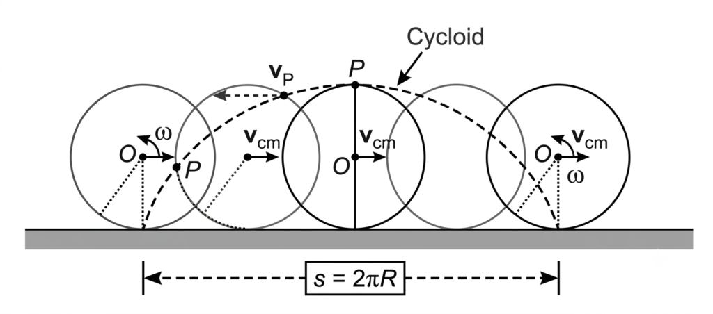
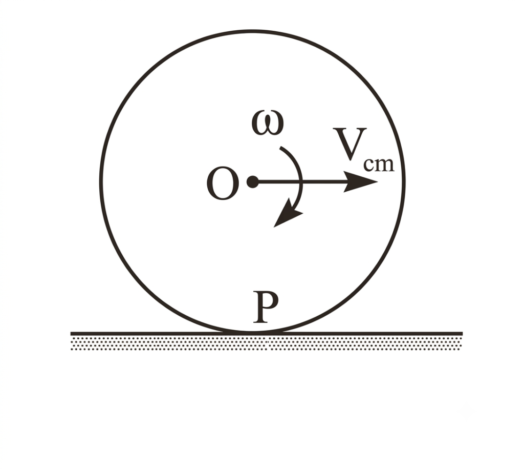
Consider a wheel moving along a straight track, the centre of the wheel moves forward in pure translation. A point on the rim of the wheel, however traces out a complex curve called cycloid. We can analyse the motion of a rolling wheel as a combination of pure translation and pure rotation.
1) In one complete rotation of wheel, the centre of mass of the wheel moves a displacement \(s = 2\pi R\). In this motion there is no relative motion between the point of contact of the moving body and the surface. If \(T\) is the time to complete a rotation, then we have
\[ V_{\text{cm}} = \frac{s}{T} = \frac{2\pi R}{T} \quad \text{or} \quad V_{\text{cm}} = V_r = \frac{2\pi}{T} R = R\omega \]
2) If \(V_{\text{cm}} = R\omega\), the wheel is in pure rolling. The velocity of the point of contact is zero.
3) If \(V_{\text{cm}} > R\omega\), wheel slips forward. The wheel moves through a distance greater than \(2\pi R\) in one full rotation.
4) If \(V_{\text{cm}} < R\omega\), wheel slips backward. The wheel moves through a distance less than \(2\pi R\) in one full rotation.
* Rolling motion = Pure translatory motion + Pure rotatory motion.
Velocity at any Instantaneous Point on the Rolling Body
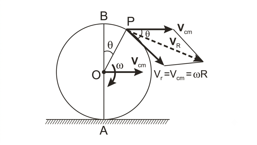
Consider a point \(x\) on a rolling body, the velocity of point \(x\) is the vector sum of velocity due to translation and rotation. Thus
\[ \vec{V}_R = \vec{V}_{\text{translation}} + \vec{V}_{\text{rotation}} = \vec{V}_{\text{cm}} + \vec{\omega} \times \vec{r} \]
or
\[ |\vec{V}_R| = \sqrt{V_{\text{cm}}^2 + V_r^2 + 2V_{\text{cm}}V_r \cos\theta} \]
or
\[ |\vec{V}_R| = 2V_{\text{cm}} \cos\frac{\theta}{2} \]
Here \(\theta\) is the angle made by the radius vector with upward vertical in clockwise direction.
Velocities at Different Points on the Rolling Wheel
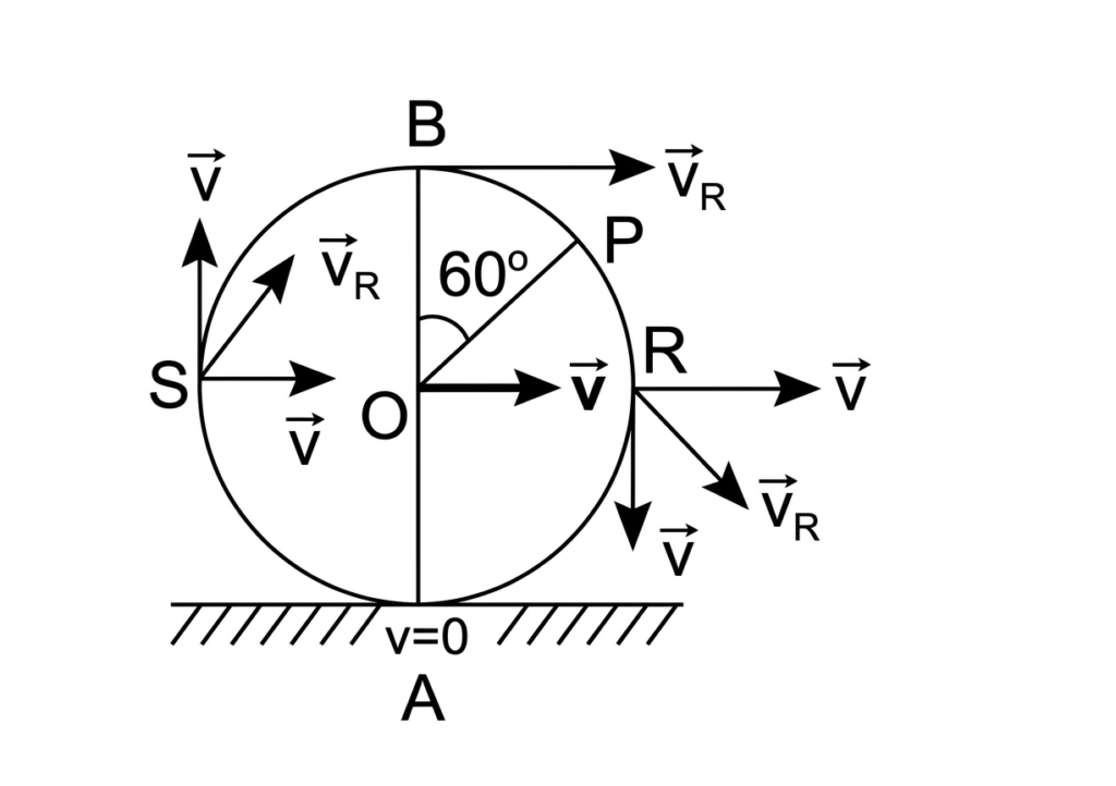
We know that for a body in pure rolling motion, the magnitude of the translational velocity of the centre of mass equals the rotational velocity at the rim:
Velocity at Key Points on the Rolling Wheel
- At Centre (O): \(V_{\text{cm}} = V\) (Pure translational motion).
- At Contact Point (A): \(\theta = 180^\circ\), \(|\vec{V}_R| = 2V \cos\left(\frac{180^\circ}{2}\right) = 0\) (The point of contact is instantaneously at rest in pure rolling).
- At Topmost Point (B): \(\theta = 0^\circ\), \(|\vec{V}_R| = 2V \cos\left(\frac{0^\circ}{2}\right) = 2V\) (Maximum velocity, moving forward at twice the speed of the centre of mass).
- At Rightmost Point (R): \(\theta = 90^\circ\), \(|\vec{V}_R| = 2V \cos\left(\frac{90^\circ}{2}\right) = \sqrt{2}V\).
- At Point P (at angle \(60^\circ\)): \(\theta = 60^\circ\), \(|\vec{V}_R| = 2V \cos\left(\frac{60^\circ}{2}\right) = \sqrt{3}V\).
Additional Note: The locus of all resultant velocity vectors across the rim points forms a symmetric velocity distribution field perpendicular to the instantaneous axis of rotation passing through point A.
Kinetic Energy of Rolling Body
A body rolling without slipping possesses both translational kinetic energy and rotational kinetic energy.
Therefore, the total kinetic energy (\(\text{KE}\)) of a rolling body is the sum of its translational and rotational kinetic energies:
\[ \text{KE} = \text{KE}_t + \text{KE}_r \]
1. Translational Kinetic Energy (\(\text{KE}_t\)):
\[ \text{KE}_t = \frac{1}{2} M V_{\text{cm}}^2 = \frac{1}{2} M V^2 \quad (\text{since } V_{\text{cm}} = V_r = R\omega = V) \]
2. Rotational Kinetic Energy (\(\text{KE}_r\)):
\[ \text{KE}_r = \frac{1}{2} I_{\text{cm}} \omega^2 = \frac{1}{2} (MK^2) \left(\frac{V}{R}\right)^2 = \frac{1}{2} M V^2 \left(\frac{K^2}{R^2}\right) \]
Letting the dimensionless parameter \(\beta = \frac{K^2}{R^2}\), we get:
\[ \text{KE}_r = \frac{1}{2} M V^2 \beta \]
3. Total Kinetic Energy:
\[ \text{KE} = \text{KE}_t + \text{KE}_r = \frac{1}{2} M V^2 + \frac{1}{2} M V^2 \beta = \frac{1}{2} M V^2 (1 + \beta) \]
Hence, total kinetic energy of the rolling body without slipping:
\[ \text{KE} = \frac{1}{2} M V^2 (1 + \beta) \]
Where \(\beta = \frac{K^2}{R^2}\) is a dimensionless quantity. Its value varies from body to body and axis to axis.
For example:
- For ring: \(I = MR^2 = MK^2 \implies \frac{K^2}{R^2} = 1 = \beta\)
- For Solid sphere: \(I = \frac{2}{5}MR^2 = MK^2 \implies \frac{K^2}{R^2} = \frac{2}{5} = \beta\)
- For disc: \(I = \frac{MR^2}{2} = MK^2 \implies \frac{K^2}{R^2} = \frac{1}{2} = \beta\)
- For hollow sphere: \(I = \frac{2}{3}MR^2 = MK^2 \implies \frac{K^2}{R^2} = \frac{2}{3} = \beta\)
K.E of the rolling body without slipping can also be written as: \(\text{KE}_{\text{rolling}} = \text{KE}_t + \text{KE}_r\)
\[ = \frac{1}{2} M V_{\text{cm}}^2 + \frac{1}{2} I_{\text{cm}} \omega^2 \quad (V_{\text{cm}} = R\omega) \]
\[ = \frac{1}{2} M R^2 \omega^2 + \frac{1}{2} I_{\text{cm}} \omega^2 = \frac{1}{2} [MR^2 + I_{\text{cm}}]\omega^2 \]
As we know \(MR^2 + I_{\text{cm}} = I_p\) is the moment of inertia of the wheel about the point of contact ‘P’ then,
\[ \text{KE}_{\text{rolling}} = \frac{1}{2} I_p \omega^2 \]
Note: Rolling motion of a body may be treated as pure rotation about an axis normal to the plane passing through the point of contact with same angular velocity.
Additional Important Relations:
- Fraction of translational KE in the total kinetic energy = \(\displaystyle \frac{1}{1 + \beta}\)
- Fraction of rotational KE in the total kinetic energy = \(\displaystyle \frac{\beta}{1 + \beta}\)
- Ratio of translational KE to rotational KE = \(\displaystyle \frac{1}{\beta}\)
Angular Momentum of Rolling Wheel
Angular momentum of a rolling wheel about an axis passing through the point of contact \(P\) and perpendicular to the plane of wheel:
\[ \vec{L} = \vec{L}_{\text{translation}} + \vec{L}_{\text{rotation}} \]
\[ \vec{L} = m(\vec{R} \times \vec{V}_{\text{cm}}) + I_{\text{cm}} \vec{\omega} \]
or
\[ \vec{L} = m\omega R^2 + I_{\text{cm}} \omega \]
or
\[ L = (I_{\text{cm}} + mR^2)\omega = I_p \omega \]
19. Rolling a Body on an Inclined Plane
Rolling of a body does not take place on a smooth inclined plane, but it takes place on a rough inclined plane.
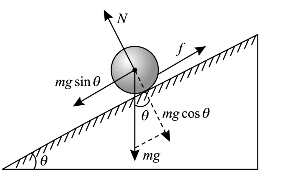
Consider a rigid round body of mass ‘m’ and radius ‘R’ placed on a rough inclined plane making an angle \(\theta\) with the horizontal as shown in figure.
The forces acting on the body are:
-
Weight ‘mg’ acting vertically downwards.
The component of the weight along the inclined plane is \(mg \sin\theta\) and perpendicular to the inclined plane is \(mg \cos\theta\).
The torque produced by the weight about the centre is \(\tau_1 = mg(0) = 0\) (Weight acts along the centre). - Normal reaction \(N\). The torque produced by the normal reaction \(N\) is \(\tau_2 = N(0) = 0\) (Normal reaction passes through the centre).
-
The static frictional force \(f_s\) acts along the inclined plane upwards.
The torque produced by the frictional force \(f_s\) is \(\tau_3 = f_s(R)\).
The resultant force normal to the inclined plane is zero because \(N\) balances \(mg \cos\theta\).
\[ N = mg \cos\theta \]
The net force acting down the inclined plane is:
\[ F_R = mg \sin\theta – f_s \]
If \(a\) is the acceleration of the body down the inclined plane:
\[ a = \frac{mg \sin\theta – f_s}{m} \quad \text{— (1)} \]
Net torque acting on the body is:
\[ \tau = \tau_1 + \tau_2 + \tau_3 \]
\[ \tau = 0 + 0 + f_s R \]
Due to this torque the angular acceleration of the body is given by:
\[ \alpha = \frac{f_s R}{I} \]
But \(\alpha = \frac{a}{R}\) and \(I = mK^2\) (where \(K\) is radius of gyration):
\[ \frac{a}{R} = \frac{f_s R}{mK^2} \]
\[ a = \frac{f_s R^2}{mK^2} \quad \text{— (2)} \]
Substitute equation (2) in (1):
\[ a = g \sin\theta – \frac{f_s}{m} \]
\[ a = g \sin\theta – \frac{m K^2 a}{R^2 m} \]
\[ a = g \sin\theta – \frac{K^2 a}{R^2} \]
\[ a \left(1 + \frac{K^2}{R^2}\right) = g \sin\theta \]
\[ a = \frac{g \sin\theta}{1 + \frac{K^2}{R^2}} \]
Since \(\beta = \frac{K^2}{R^2}\), we get:
\[ a = \frac{g \sin\theta}{1 + \beta} \]
Static frictional force:
\[ f_s = g \sin\theta \left[\frac{\beta}{1 + \beta}\right] \quad \text{— (4)} \]
a) Condition for pure rolling without slipping is:
\[ f_s \le f_L \quad (f_L = \mu_s N = \mu_s mg \cos\theta) \]
\[ g \sin\theta \left[\frac{\beta}{1 + \beta}\right] \le \mu_s mg \cos\theta \]
Coefficient of static friction is:
\[ \mu_s \ge \tan\theta \left[\frac{\beta}{1 + \beta}\right] \]
Ex: For solid sphere \(\beta = \frac{2}{5} \implies \mu_s \ge \frac{2}{7}\tan\theta\)
b) Velocity of the rolling body (without slipping) on reaching the bottom of the inclined plane is:
\[ \text{PE}_A = \text{KE}_B \]
\[ mgh = \frac{1}{2} mv^2 [1 + \beta] \]
\[ v = \sqrt{\frac{2gh}{1 + \beta}} \quad \text{or} \quad v = \sqrt{\frac{2gl \sin\theta}{1 + \beta}} \]
(Since \(\sin\theta = \frac{h}{l} \implies h = l \sin\theta\))
c) Time taken by the rolling body to reach the bottom of the plane is:
\[ l = ut + \frac{1}{2} at^2 \quad (\text{where } u = 0, \text{ so } l = \frac{1}{2} at^2) \]
\[ t = \sqrt{\frac{2l}{a}} \]
Substituting \(a = \frac{g \sin\theta}{1 + \beta}\):
\[ t = \sqrt{\frac{2l(1 + \beta)}{g \sin\theta}} \quad \left(\text{since } l = \frac{h}{\sin\theta}\right) \]
\[ t = \frac{1}{\sin\theta} \sqrt{\frac{2h}{g}(1 + \beta)} \]
Hence, \(t \propto \sqrt{1 + \beta}\)
* For sliding bodies \(\beta = 0\):
\[ t = \sqrt{\frac{2l}{g \sin\theta}} = \frac{1}{\sin\theta} \sqrt{\frac{2h}{g}} \]
Smaller the \(\beta\), smaller the time taken by the rolling body to reach the bottom of the inclined plane.
Note 4.42:
(a) A ring, disc, solid sphere, and hollow sphere are allowed to roll down from the top of an inclined plane at the same instant. The solid sphere reaches the ground first and finally the ring.
The sequence in which they reach the ground is:
- Solid sphere
- Disc
- Hollow sphere
- Ring
\[ (\beta_{\text{solid sphere}} < \beta_{\text{disc}} < \beta_{\text{hollow sphere}} < \beta_{\text{Ring}}) \]
(b) If in the above case all the bodies are allowed to slide instead of rolling, then all the bodies reach the bottom of the inclined plane at the same time.
\[ t = \sqrt{\frac{2l}{g \sin\theta}} \quad \text{is same for all bodies.} \]
Note 4.43: Friction is responsible for the rolling motion, but work done (or dissipation of energy) against friction is zero as there is no relative motion between body and the surface at the point of contact.
Note 4.44: In order to complete a vertical circle of radius ‘r’ at the bottom of the inclined plane, the height from which the rigid body is to roll down is:
\[ \text{PE}_A = \text{KE}_B \]
\[ mgh = \frac{1}{2} mv^2 [1 + \beta] \]
If velocity at ‘B’ is \(v = \sqrt{5gr}\) then the body completes a vertical circle.
\[ mgh = \frac{1}{2} m (5gr) (1 + \beta) \]
\[ h = \frac{5}{2} r [1 + \beta] \quad \text{or} \quad h \ge \frac{5}{2} r [1 + \beta] \]